Problem statement
The design of high-lift machines is one of the most demanding concerns in aerodynamic study. The requirements for the structure of these machines depend entirely on the main disciplines in aeronautical study. These include aerodynamics, aeroacoustics, structures, systems and kinematics. The chief objective of the systems/structures is the enhancement of lift coefficient during take-off or when landing. The reason for this is to lessen flight velocity in low altitude flying. These systems (high-lift systems) are supposed to be lightweight, simple to set in motion and easy to maintain.
In relation to high lift systems, aerodynamic technology has to focus on the impacts of air flow, and predominantly when it interrelates to the high lift objects. Having knowledge on air flow/flow field around these devices facilitates the computation of forces and moments having impact on the devices. In the design of high-lift machines, “typical properties calculated for a flow field include velocity, pressure, density and temperature as functions of position and time”. (Von Karman, 2004)
For transonic transport on the other hand, the structure of high lift designing is a vital constituent in configuring designs. To acquire rational field performance as well as attaining effective transonic cruise, a highly refined high-lift system design will be required. In reference to the aircraft Boeing B-777:
A 0.10 increase in lift coefficient at constant angle of attack is equivalent to reducing the approach attitude by one degree. For a given aft body to ground clearance angle, the landing gear may be shortened for a savings of airplane empty weight of 1400 1b. A 1.5 percent increase in maximum lift coefficient is equivalent to a 6600 1b increase in payload at a fixed approach speed. A 1 percent increase in take off L/D is equivalent to 2800 1b increase in payload or a 150 nm increase in range (Garner, Meredith, & Stoner, 2001).
For fighter planes, the devices are also engineered to facilitate efficient maneuverability. For STOVL, V/STOL aircrafts, these systems are also decisive. These aircrafts use the propulsion systems in helping generate the lift as well. At first, I felt it was uncharacteristic to design fighter planes or practically all armed forces planes, to run on traditional landing strips. One thing the enemy can possibly know is the precise location of the landing strip, and therefore an STOVL’s ability appears to be vital in severe confrontations.
The chief concepts in this subject are encompassed in early compressibility, vital current high-lift systems and the significance of the high cost of manufacturing. On the other hand, “multi-element airfoils, high lift for a single airfoil and the use of “blowing” in some form of powered lift are some of the categories of challenges embodied in this subject.” (Mason, 2001) When doing computation, immediate viscous consideration is required. This is in contrast with characteristic airfoil analyses and designs in which a few insights can generally be achieved disregarding viscous impacts. The prediction of high lift is made almost totally by use of Navier-Stokes codes.
On airfoils, the main example used to acquire high-lift on single element airfoils is the design of Liebeck on high-lift airfoil together with Stratford’s pressure recovery outline of its distribution. In comprehension of the physics behind the multi element air foil, one has to have comprehensive knowledge in the following elements, “the slat effect, the circulation effect, the dumping effect, off the surface pressure recovery and the fresh boundary layer effect” (Smiths, 2008).
Current high-lift systems are a lot more complex with a lot of constituents and multi-bar linkages. Computational-fluid-dynamics is employed in designing these multifaceted systems; although the principal design of airfoil systems cannot always create preferred aerodynamic qualities for precise applications. Consequently, the optimization system is needed to develop on the aerodynamic qualities under any constraints. Optimization techniques also do have a dynamic responsibility in manufacturing blueprint; and particularly in automotive industries.
The objective of this proposal therefore, is to develop an airfoil design and optimization system that can modify an airfoil shape (section geometry) yielding improved aerodynamic performance in terms of maximum lift to drag ratio under landing flight conditions.
Computerizing the optimization progression can considerably shorten development product lifecycle and bring forth improved designs compared to conventional tactical design alteration approaches. An efficient and effective sleek optimization technique is developed by a combination of high-fidelity commercial CFD tools with mathematical optimization techniques. This system not only offers a consistent, automated optimization tool for blueprint engineers, but also considerably diminishes the cost and the manufacturing time for a design procedure.
This development encompasses the amalgamation of the CFD (elevated fidelity commercial) tools fluent with numerical optimization techniques to morph high lift system. Figure 1 displayed below, shows the differences between conventional and proposal strategy. In the later, we will carry out morphing/grid deformation directly within the fluent code exclusive of geometry rebuilding and the mesh with an exterior tool. Direct search procedure approach for instance the Simplex, Powell, Compass, Rosenbrock, and Torczon are available. The user can select any of these to use in optimizing of aerodynamic shapes attributes.
In a synopsis, the developed system is an optimization tool which exploits the power of commercial CFD software to determine the most efficient shapes of airfoil as per designer requirements.
Motivation behind the research
Airfoil design and optimization is not a new field in aerodynamics. From early stages of flight development, researchers, designers and engineers have been engrossed in designing airfoils which can generate most favorable performance as per their specific aircraft requirements. They have relied mostly on experimental results and the information about speculative fluid dynamic concepts. Recently, new advancements in commercial CFD software and tools have facilitated designers to achieve aerodynamic characteristics of innovative airfoil designs devoid of the need of monotonous experiments. Parallel to these forward moves, there are the optimization systems capable of tuning design parameters automatically to optimize the performance of the designs. This presents a great incentive to build up an airfoil design optimization tool by coupling commercial CFD software and an optimizing method. Additionally, the airfoil’s design and optimization systems are forever essential due to the following reasons:
- Standard and pre-designed airfoils cannot at all times be used as they may not create preferred aerodynamic distinctiveness for exact applications.
- Geometry is very significant for an airfoil. Even slight changes in this can bring forth major changes in lift and drag, so optimization is constantly necessary.
- Limitations of present cataloged airfoils might not be appropriate to new and inventive designs.
- A programmed computation of optimal airfoil shape can be constant for divergent requirements.
A design optimization method is given that combines a computationally capable Navier-Stokes system with numerically optimization algorithms. The design technique develops the aerodynamic capability of airfoils subject to specific design purposes and constraints. Modern advancement in computer technology and computational-fluid-dynamics has allowed the employment of the Navier-Stokes equation in the design process to contain the non-linear, rotating, and viscous-physics of transonic flows. “Using numerical optimization guarantees that a better design will be produced even with strict design constraints. The method is demonstrated with several examples at transonic flow conditions.” (Eyi, Hagers & Lee, 1994)
Literature Review
Fundamental Concepts
Air and water, all have a quantity of viscosity. Birds and planes fly and boats sail for the reason that there is fluid viscosity. The impacts of viscosity exist in the areas near airfoil surfaces identified as boundary layers, because of skin resistance; drag is formed on the surface. In low speed flows for instance, the fluid on the outer surface boundary coating can be considered to be lacking viscosity.
A quantity of air-flow over the top of the airfoils is large for the reason that, there is the movement flow field. “This quantity of air passes through, in between each pair of streamlines” (Clancyl, 2005). Close to the leading edge of an airfoil, where streamlines get closer, the momentum of flow augments. The result of this is low pressure. “On the lower surfaces where streamlines are more apart, the flow lessens and pressure becomes elevated” (Clancyl, 2005). As a result, low pressure on top and high pressure at the base produces the lift for an airfoil.
Basic Airfoil Theory
Airfoil shaped bodies that are moved through fluids, produce aerodynamic forces. The components of these forces at right angles to the way of movement are what are referred to as lift. The factors corresponding to the bearing of movement are the drag. “Subsonic flight airfoils have a characteristic shape with a rounded leading edge, followed by a sharp trailing edge, often with asymmetric camber. Foils of similar function designed with water as the working fluids are called hydrofoils” (Clancyl, 2005).
The lifting on airfoils is principally the effect of its shape and particularly the camber together with the angle of attack. When any of these is positive, the resultant flow-field acting on an airfoil has superior standard speed on the upper surfaces as compared to the lower surfaces. The speed differences essentially go together with pressure differences. This is shown in Bernoulli’s theory for incompressible inviscid flows that consecutively generates lift force. This lift can again be correlated directly to an average top or bottom speed disparity; this can be done devoid of bringing pressure into play. The principle employed here is the Kutta-Joukowski theory and the conception of circulation flow.
The resulting force applied on a body by air is referred to as aerodynamic force, and this is due to the relative movement linking the body and the fluid. This force occurs from two sources:
- The force due to the pressure on the surface of the body
- The force due to viscosity, also known as skin friction
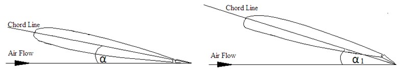
Figure 2 below displays an aerodynamic force action through the centre of pressure. With proportioned airfoils, the location of the center of pressure is permanent and matches up to the airfoil’s AC (aerodynamic centre). Conversely, with cambered airfoils, the location of the center of the pressure differs with the alteration in angles of attack. “The angle of attack (α) is the angle between the airfoil’s chord line and the direction of airflow velocity (V).” (Anderson, 2004)
Lift Force
“A fluid flowing past the surface of a body exerts a surface force on it” (Anderson, 2004). Lift is described as the constituent of this king of force which is vertical to the approaching flow bearing. “It contrasts with the drag force, which is defined to be the component of the surface force parallel to the flow direction” (Anderson, 2004). As shown by Anderson (2004), “if fluid is air, the force is called aerodynamic force. Aerodynamic lift is commonly associated with the wing of an aircraft, although lift is generated by the likes of propellers and hydrofoils”.
Lift IS also a kind of force which directly counters the weight of an aircraft and holds up the plane in the air. Most part of the lift-force is produced on a standard aircraft by its wings. Lift is a perfunctory aerodynamically created force formed by the movement of the plane through the air. Since lift is a kind of force, it’s a vector, possessing a magnitude and a bearing related with it. Lift operates through the middle of the pressure of a body and is directed at right angles to the bearing of the flow. The enormity of the particular lift depends on a number of factors that include the figure, dimension, and speed of an aircraft.
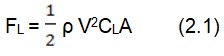
Where:
- FL is the Lift force in Newton
- ρ is the air density in kg/m3(The standard density of the air is 1.225kg/m3)
- V is the airflow velocity in m/s
- A is the wing area in m2
- CL is the lift coefficient – a dimensionless constant
Drag Force
Drag is a complex phenomenon and clarifying it from a theoretical perspective centered completely on essential principles is extremely intricate. This is an issue which is best researched by conducting tests.
As an aircraft soars through air, there is a different aerodynamic-force present. “The air opposes the movement of the plane and the consequent opposing force is what drag is” (Blevins, 2003). This is directed along and contrasts to the flight bearing. Similar to lift, there are a number of aspects that impact on the scale of the drag force as well as the outline of the plane, air viscosity, and the speed of the plane. “Just like lift, there is the putting together of all individual constituents of drags and combining them into one airplane drag magnitude. Again like lift, this force acts through the airplanes’ center of pressure” (Blevins, 2003).
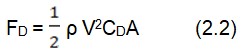
Where:
- FD is the Drag force in Newton
- ρ is the air density in kg/m3 (The standard density of the air is 1.225kg/m3. )
- V is the airflow velocity in m/s
- A is the wing area in m2
- CD is the Drag coefficient – a dimensionless constant
The formula below is an explanation of force and substitute as shown by Elerts (2006) on Bernoulli’s equation about pressure.
Factors affecting pressure drag are easy to make out and understand. But the intricacy is found in the details. Drag is enhanced with the mass of fluid P. Extra density means extra mass and hence extra inertia and therefore extra resistance in getting away from the way. The 2 magnitudes are of direct proportions R ∝ ρ.
The drag is enhanced with area (A) although this concept is subject to discussion.
In the conception of this model A is the cross section region projecting in direct movement. Taking the cross-section of the body in the bearing of its movement is like the most logical definition of A. again it is important to note that, surface-area is not significant when dealing with drag-force, but it is significant if one is to deal with viscous drag (Blevins, 2003).
Drag is enhanced with velocity (V). A stationary body in regard to the fluid cannot experience drag-force. When motion starts resistive force will be realized. When the body moves even faster the resistive forces becomes grater. The hardest part of the association is found in the complete way velocity impacts on drag force. The main questions arising from this concept are; “the two quantities directly proportional? Does drag increase as the square of speed? Then square root of speed and the cube of speed conception. Essentially, drag should be proportional to the square speed R ∝ v2” (Blevins, 2003). This part is still subject to debate because such relationships are verified by authenticated physical experiments but not plain theory.
Drag is manipulated by other aspects which include, “the body’s shape, texture, viscosity (which results in viscous drag or skin friction), compressibility, lift (which causes induced drag), boundary layer separation, and so on” (Blevins, 2003). The mentioned aspects can be dealt upon independently in a more absolute theory on drag-force. They can again be piled in 1 colossal falsify factor (coefficient of drag Cd) R ∝ Cd.
When merging all these aspects, a theoretically restricted but empirically sensible equation will be yielded. This equation will be R = ½ρCAv2
Angle of attack, Lift and Drag
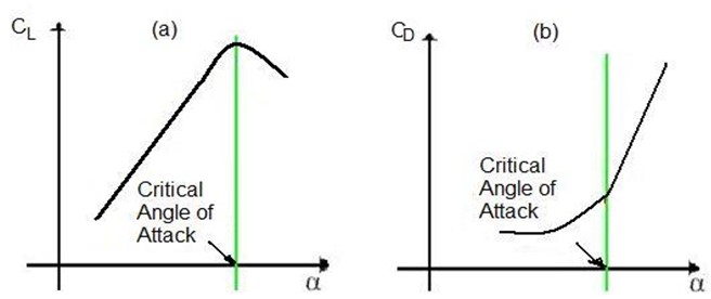
“The angle of attack portrays angles between the chord lines of wings on fixed wing aircrafts and vectors that represent relative motions between airplanes and the ambiance” (Elerts, 2006). In relation to lift, “the lift coefficient of a fixed-wing aircraft varies uniquely with angle of attack. Increasing angle of attack is associated with increasing lift coefficient up to the maximum lift coefficient, after which lift coefficient decreases” (Elerts, 2006). As the angel enlarges, severance of air flow from the top surface on the wing is more distinct. This leads to lessening the rate of enhancement on lift coefficient. This angle impacts on lift and drag as no such angle merges utmost lift and least drag. A 0 angle creates the smallest amount of drag, but also 0 lift. “Lift is increased as the angle of attack increases until a critical angle is reached when drag exceeds lift and the object stalls” (Elerts, 2006).
On the other hand, an angle that creates utmost lift-coefficient is a critical angle of attack. Below this as attack angle is augmented, air starts to gush less efficiently on the top surface of an airfoil then it starts to divide from the upper-surface. On a lot of air foil outlines when the attack-angle is enhanced, the top surface parting position of the gush moves starting on the trailing edging to the lead edge. As per the critical-angle-of-attack flowing on the top surface, “is more separated and the airfoil or wing is producing its maximum coefficient of lift. As angle of attack increases further, the upper surface flow becomes more and more fully separated and the airfoil/wing produces less coefficient of lift” (Elerts, 2006).
On top this angle, the plane is in a condition called stall. A fixed wing plane by description is stalled on top rather than under a specific airspeed. The speeds upon which the plane stalls vary with the mass of the plane, load factors, bank-angle, gravitational pull of the plane among other aspects. Conversely, the plane constantly stalls at an identical critical angle of attack. This angle is characteristically approximately 15° for a lot of airfoils
The coefficients in opposition to the angle of attack as displayed in the figure 3 below are a suitable way of illustrating the aerodynamic features of an airfoil. Originally CL and CD augments as the angles of attack is enhanced. At a particular point, the lift starts to go down as the drag is enhanced sharply. This position is described as the CAA (Critical Angle of Attack). If this angle (angle of attack) is enlarged past the CAA, at a particular point every lift will be misplaced as the drag is further increased, at which point the wing is considered to stall.
As shown in figure (4), the deflection of a flight control surface (flaps) the chord line will modify, which will increase of angle of attack without stalling the wing.
When solid bodies are put in fluid-flow where a symmetrical condition is reported, the bearing of the drag force on these bodies does not correspond with the bearing of the uninterrupted flow. This theory is what makes flight feasible. “Discussion on drag, lift and angle of attack normally start with the introducing an airfoil” (Kermode, 2002).
The eventual goal of an airplane’s high-lift system blueprint, shows a simple arrangement for prescribed restraints that meet lift and drag requirements. This are normally articulated in term off utmost L/D and maximum CL1.
Currently, design for transport high-lift systems relies on widespread utilization of wind-tunnel experiments in concurrence with uncomplicated CFD (computational fluid Dynamics analysis). The computational fluid dynamics tools normally encompass 3 dimensional inviscid techniques to recognize vital wing sections. After that the high-lift design systems and optimization is carried out with 2D information based on preceding designs. Important developments can still be arrived at; this is by the employment of highly developed computational technique in conjunction with optimized techniques of designing superior systems at low costs.
As current airplane design tends to be even more multifaceted to outperform preceding models, new technology in system designing amalgamation and optimization becomes even more significant. This paper has illustrated the necessary constituents in aerodynamic high-lift optimization. Maximum-lift, drag, and momentous coefficients are acceptably calculated. These techniques are effectively validated by reflecting on inverse designing setbacks. This approach is subsequently applied to optimizing a multi element airfoil design for utmost L/D, and in designing an airfoil’s shape for utmost Cmax at Rc=2x 10⁶. In this study, a lot of development in purposeful functionality is evident which makes this demonstration potentially viable in designing environments.
References
Anderson, J. (2004). Introduction to fight. London: McGraw hill.
Blevins, Robert D. 2003. Applied Fluid Dynamics Handbook. London: Krieger Publishing Co.
Clancyl, J. (2005). Aerodynamics. London: Pitman Publishing Limited.
Elerts, G. (2006). Aerodynamic Drag. Physics hyper-textbooks Publishers.
Eyi, S., Hagers, J. O. & Lee, K. D. (1994). Airfoil Design Optimization Using the Navier-Stokes Equations. Journal of Optimization Theory and Applications, 83 (3), 447-461.
Garner, P., Meredith, P.T., & Stoner, R.C. (2001). Areas of future CFD developments as illustrated by transport aircraft applications. AIAA Paper, 1, 91-1527.
Kermode, A.C. (2002). Mechanics of flight. London: Pitman Publishing Limited.
Mason, J. (2001). Airfoil Design Optimization. London: Pitman Publishing Limited.
Smiths, A. (2008). “High-Lift Aerodynamics,” 37th Wright Brothers Lecture. Journal of Aircraft, 12 (6), 162-198.
Von Karman, T. (2004). Aerodynamics: Selected Topics in light of Their Historical Development. New York, NY: Dover Publications.