Introduction
Autonomous unmanned ground vehicles have been known to significantly improve efficiency and safety in applications stretching from transportation to ware fare. In order to achieve these benefits to the fullest, unmanned vehicles should be developed to operate more effectively in unstructured environments and conditions (Zweiri & Seneviratne & Althoefer 765). Such vehicles should have the ability to effectively maneuver in highly unstructured environments like forests, which have numerous potential obstacles (Yoshida & Hamano 15). Forested areas are considered one of the highest unstructured environments due to a number of factors which include the following:
- They have a high number of varied and potential obstacles
- Forested environments have a high-level of complexity in its visual fields
- Forested areas have a poor GPS signal because of the high overhead interface in the forests (Tan et al 30).
In understanding the concept of unmanned ground vehicles, it is of paramount importance to understand other areas that employ the use of unmanned technology. One such area of application is the unmanned air vehicles. Unmanned air vehicles have some advantages which include but not limited to the following: have greater mobility capabilities, have extended perception and good tracking (Iagnemma et al 17).
For the purposes of this research paper, unstructured environments will basically be used to refer to those physical environments that do not have a regular layout or structure. Unmanned ground vehicles can be defined as those vehicles that have the ability to navigate through various terrains with minimal human assistance (Hutangkabodee et al 33).
There are two major categories of unmanned ground vehicles. The two broader categories are remote controlled, and autonomous unmanned ground vehicles.
Remotely operated ground vehicles
A remotely controlled UGV can be defined as a vehicle that is operated remotely by a human being over a communication link. The operations of such vehicles are determined by an operator, who directly observes the visual images of the moving body, and the surrounding information by use of a camera (Song et al 103). Remote operated UGV have found many uses in the current world which include but not limited to the following uses:
- These vehicles are used to replace human beings in hazardous situations like bomb, and explosives disabling operations.
- They are used in peace keeping operations, check point operations, enhance police and military operations in urban areas, and ground surveillance operations (Song et al 105).
Autonomous unmanned ground vehicles
An autonomous UGV is a vehicle that has the capability of operating without being controlled by an operator. The vehicle does not require to be controlled from a communication channel. The vehicle is capable of obtaining information about the environment and maneuvering around the unstructured terrain (Zweiri & Seneviratne & Althoefer 764). Autonomous UGV have the following characteristics:
- Work for a considerable amount of time without human intervention and can navigate from point to point without human navigation assistance (Zweiri & Seneviratne & Althoefer, 765).
- They can gain information about the environment in which they are operating
- They will always avoid environments that are harmful to humans and the equipment itself, except for those conditions that are part of its design specifications.
- They have the capabilities of automatically detecting errors within its systems and automatically adjusting to accommodate these errors (Zweiri & Seneviratne & Althoefer, 767).
- Has the ability of automatically detecting objects and automatically adjusting to such object and obstacles without the assistance of an operator (Iagnemma et al 40).
The above illustration basically points out to the two broader categories of UGV. Despite the category of the UGV, there is dire need to develop an obstacle detection and controller system that will enhance the efficient and effective performance of such unmanned ground vehicles.
Most unmanned ground vehicles are remotely controlled and will always depend on the trajectory sensors that provide intelligent information to the vehicle. In such kinds of applications, the ability of unmanned ground vehicles to navigate through rough and unstructured environments is of paramount importance (Iagnemma & Shibly & Dubowsky, 60).
Such vehicles require an intelligent system that will provide high intelligence information in order to facilitate the navigation through such environments (Zweiri & Seneviratne & Althoefer, 767). This directly underpins the fact that there is need to develop a controller for unmanned ground vehicles which will operate in such environments. The development of such a controller will enhance reduction in cross-track errors during the trajectory process (Calttabiano & Muscato 703).
The controller developed should be in a position to detect and avoid obstacles just in due time. The controller should then trigger a response depending on the nature of the obstacle detected. Obstacle detection has been an area of study by many scientists in the recent past (Zweiri & Seneviratne & Althoefer 767). Various algorithms have been developed in order to enhance error free obstacle detection mechanisms by the intelligent sensors. For example, according to Scheding et al (59) , the National Institute for science and technology developed an obstacle algorithm to aid in the process of obstacle detection in unmanned ground vehicles.
The algorithm developed uses an amalgam of sensor- based and grid-based obstacle detection as well as mapping techniques. The above obstacle detection method consists of two major sections. They are obstacle detection section, and the mapping section (Talukder et al 710).
The obstacle detection is the first step towards detecting an obstacle which employs the use of a ladar sensor. The algorithm then converts the image from the ladar sensor into Cartesian coordinates in the coordinate frame of the sensor. The sensor then uses this information to detect objects and obstacles (Zweiri & Seneviratne & Althoefer 766). The second phase is the mapping section, which will project obstacle points into a grid-based map. The map is then taken to the 4D real-time control system (4D- RCS) which will generate a passable path for the unmanned vehicle (Carlson & Murphy 428).
Other researchers and manufacturers of unmanned ground vehicles have been able to employ the use of entropy in detecting obstacles. Entropy is a measure of information where the information obtained is used to generate a map of the environment. The information obtained is normally computed offline using a priori map. The visual and ultrasound data captured by a mobile robot is used to construct a map for direction-finding (Carlson & Murphy 430).
The entropy technique utilizes the optimal sensor placement techniques in detecting obstacles and obtaining intelligent knowledge for navigation. Various scientists have noted that the entropy technique has some limitations associated with its use. They include but are not limited to the following limitations: poor pattern recognition, image interpretation and matching areas inline with outdoor robotic navigation (Talukder et al 712).
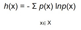
Entropy technique can be defined as a measure of the improbability which is associated with a probability density function. The entropy technique was first used and applied in classical thermodynamics. Ever since its inception, the technique has been applied in various sectors including but not limited to the following sectors: communications, systems theory, and robotics sensing (Carlson & Murphy 431). The entropy of a probability distribution which is denoted by p(x) well-defined on a random variable x is the expected negative value of a log-likelihood and is denoted by the following expression (Iagnemma et al 69).
h(x) = E {-lnp(x) where E represents the mathematical expectation operator. h(x) is the entropy which is a measure of the middling uncertainty of random variables. It can also be used to represent the compactness of the probability distribution, p(x). it cans also be used to represent a measure of informativeness of the distribution. The entropy is minimum when information is maximum. The entropy for discrete random variables is given by the following expression (Carlson & Murphy 428).
The above information can be re-written as:
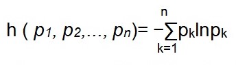
where: pk can be defined as the probability which is associated with the kth event. Entropy can be used to measure the information gained from a selection of a definite event among several events. From the above equation, it is evident that, h ( p1, p2,…, pn) is maximum when pk = 1/n and k=1,….., n, which implies that, a uniform probability distribution will always yield to a maximum entropy, hence minimum information (Iagnemma et al 39).
The gray level histogram which is obtained from the sensed images is used to determine the probability distribution such that:
pi = Npi/N ; i = 1,…,Ng where Npi is the number of pixels in the image with a gray level of i, and N is the total number of pixels in the image. Ng represents the number of gray levels. The lower the entropy, the higher the information content of the sensed image.
The other major domain and concern in the unmanned group vehicles is the position estimation. Position estimation has found various applications in the following domains; terrestrial, marine applications, space navigation, and aeronautic. Position estimation can be approached by two major approaches which are the relative position approach and the absolute position approach (Iagnemma & Shibly & Dubowsky 78).
The relative position approach
Relative position approach involves measurements that are internal to the moving equipment’s. Relative position technique produces a position relative to a previous position. This method involves the use of a dead reckoning technique also known as deduced reckoning. This technique has been used on various mobile robots for ground levels, which can either be wheeled, tracked, or legged. When used in wheeled robots, the underlying technique is referred as odometry (Iagnemma & Shibly & Dubowsky 74).
Odometry approach will count the revolutions made by the wheels and uses the knowledge from the wheels to determine and calculate the distance travelled using the radius of the wheels. To enhance the accuracy of the odometry technique, some sensors are used along with the odometry technique (Carlson & Murphy 430). The sensors can be tilt sensors like an inclinometer. Accelerometers are used to determine the distance travelled by the robot while gyroscopes are used to determine the attitude hence determining the relative position estimation. The problem within relative position estimation is that errors grow over time (Zweiri et al 431)
The second approach towards determining and estimating the position is the absolute position estimation. Absolute position estimation is concerned with determining the measurements of features that are outside to the moving equipment. This approach will definitely produce a measurement which is relative to an exterior reference system. Absolute estimators are more dependable in the sense that, errors do not grow with time. The major disadvantage of absolute position estimation is that the systems are more complex, and are prone to failure due to the complexities in the system (Zweiri et al 425)
Most absolute positioning systems rely on the global positioning system which is provided by the satellites. The global positioning system is a cheap method and technique of determining the absolute position of external features. The global positioning system has some disadvantages associated with it which include but not limited to the following disadvantages: the precision, and the accuracy of the system is not dependable unless it is used and operated with a differential receiver which is located far away from the moving equipment (Carlson & Murphy 433). The second disadvantage is that global positioning system performs poorly in mountainous areas, jungle, and urban areas due to the presence of multipath effects. Also, the system fails underground and indoors environments where the satellite signals cannot be reliably detected (Song et al 105).
Another approach which can be used in absolute positioning estimation is the Backpacker’s problem. This technique finds the position and orientation of a feature with respect to landmarks. The technique uses a topographical map, to determine the position of an image which was taken from some location in the mapped area. Mariners mainly use this kind of approach. For example, the militants use a sextant to determine the current viewing system (Zweiri et al 431)
Positioning is of paramount importance in object detection because it will determine how the moving objects will maneuver around obstacles. Hence, a good positioning algorithm should be adopted. Such an algorithm should have the capabilities of detecting obstacles with clear precision. Such a clear object detection precision is not only obtained by adopting a good detection algorithm, but also by using clear sensors that have a better image capture resolution (Yoshida & Hamano 49).
Conclusion
In conclusion, unmanned ground vehicles offer a reliable and safer solution incases where human life is a threat. For example, in detonation of dangerous explosives, and in case there is fierce war. Such vehicles have the ability to maneuver around in unstructured terrains. The ability to effectively maneuver in such unstructured terrain will largely depend on the accuracy and sensitivity of the sensors and the control unit that is fitted to the system.
The design of an intelligent control system is quite a daunting task that requires a lot of expertise knowledge in the design, development and testing stages. The testing stage may involve various prototyping tests which are aimed at obtaining the best intelligent task. Hence, much consideration and care have to be taken into account in the design of a control system. Also, incase of the remote controlled UGV, the channel of communication must be carefully selected in order to avoid the operator losing control of the unmanned ground vehicle. Poor channel of communication will basically mean poor signal reception, hence losing control of the unmanned ground vehicle. On the other hand, a good channel of communication will basically indicate that there is a good signal reception; hence, an operator has full control over the unmanned ground vehicle.
Works Cited
Calttabiano, D & Muscato, G: A Comparison between different traction control methods for a field robot, IEEE/RSJ International Conference on Intelligent Robots and Systems: 702-707, Switzerland, October, 2002. Print
Carlson, J. Murphy, R. R. How UGVs Physically Fail in the Field, IEEE Transactions on Robotics, 21.3 (2005): 423-437.Print
Huntsberger, T Rover Autonomy for Long Range Navigation and Science Data Acquisition on…….NB-THIS REFERENCE LACKED THE YEAR SO I DID NOT USE IN THE INTEXT REFERENCING. Hutangkabodee, Suksun & Zweiri, Yahya & Seneviratne, Lakmal & Althoefer, Kaspar. Soil parameter identification and driving force prediction for wheel-terrain interactions, International Journal of Advanced Robotic Systems, 5.4 (2008): 425-432. Print
Iagnemma, Karl & Shibly, H & Dubowsky, S: On-Line Terrain Parameter Estimation for Planetary Rovers, 2002 IEEE International Conference on Robotics and Automation, ICRA’02, 2002. Print
Iagnemma, Karl & Shibly, H & Rzepniewski, A & S. Dubowsky: Planning and Control Algorithms For Enhanced Rough-Terrain Rover Mobility. Proceedings of the Sixth International Symposium on Artificial Intelligence, Robotics and Automation in Space, i-SAIRAS, 2001. Print
Scheding, S & Dissanayake, G & Nebot, E.M & Durrant-Whyte, H. An Experiment in Autonomous Navigation of an Underground Mining Vehicle; IEEE Transactions On Robotics and Automation, 15. 1(1999). Print
Song, X & Song, Z & Seneviratme, Lakmal & Althoefer, Kaspar. “Optical Flow-Based Slip and Velocity Estimation Technique for Unmanned Skid-Steered Vehicles,” IEEE/RSJ Int. Conf. Intelligent Robots and Systems, 2008, 101-106. Print
Talukder, A et al.: Autonomous terrain characterization and modelling for dynamic control of unmanned vehicles, IEEE/RSJ International Conference on Intelligent Robots and Systems: 708-713, Switzerland, 2002. Print
Tan, Choopar & Zweiri, Yahya & Althoefer, Kaspar & Seneviratne, Lakmal. On-line Soil Property Estimation forAutonomous Excavator Vehicles. Technical Report, Department of Mechanical Engineering: KCL, 2002. Print
Yoshida, Kazuya & Hamano, Hiroshi. Motion Dynamics of a Rover with Slip-based Traction Model, IEEE International Conference on Robotics and Automation, ICRA’02, 2002.Print
Zweiri, Yahya & Seneviratne, Lakmal & Althoefer, Kaspar. Parameter estimation for Excavator Arm using Generalized Newton Method. IEEE Transactions on Robotics, 20. 4 (2004): 762-767.Print.