Introduction
The design process of complex systems includes many stages. The stages of operational specification modeling and system performance modeling are two very important stages in the design life-cycle and their importance is growing as they particularly help produce the initial definition of the system. The quality of the initial definition can significantly affect the product cost, reliability, total design cycle time, and the time to market the final product. This paper takes on these two stages of digital system design under the same simulation environment. This unification is possible by integrating the operational specification model and the performance model for a given system under design so that the two models can be simultaneously simulated and analyzed in a synergistic manner. Such integration enables a novel design methodology that makes specification modeling an integral part of the design process.
Operational Specification is an executable specification capable of simulating the required external behavior of the system under consideration (Habib S., 2003; Harel et. al., 1987). An operational specification model simulates the desired product behavior and can be treated as a very early prototype of the final product. Such prototypes enhance communication among and within customer and designer groups, thus helping to bridge the gap between the specification and design.
Performance modeling, on the other hand, is used to make quantitative predictions and evaluations of system performance during the design, development and maintenance stages. A useful insight into the structure and behavior of the system is also obtained during such a phase (Sarkar et. al., 1994).
In the last decade, the digital design process has undergone rapid change. Traditionally, design engineers created digital systems pictorially and built hardware prototypes to check their logic. With the advent of hardware description languages (HDLs) and synthesis tools [13, 45], software prototypes of digital systems are built and checked instead. The designer translates the system specification to an HDL program which is then input to a synthesis tool that automatically produces a gate-level circuit. The design of Application Specific Integrated Circuits (ASICs) has dramatically benefited from this development. Because a high percentage of ASIC designs is Digital Signal Processing (DSP) circuits [49], this new design process has had its greatest impact in the DSP area.
The VHISC Hardware Description Language (VHDL) [14] is a popular hardware description language in today’s electronic industry. It was designed to be not only a hardware description language but also a system design language. VHDL has the capability to model digital circuits at various levels of abstraction, which is extremely useful in the DSP area. With VHDL, DSP designers frequently start with real number models, which are then converted to fixed point integer models and finally to bit-vector models that are synthesizable. Also, behavioral synthesis tools are emerging which process the VHDL code programmed at a high level of abstraction and produce the gate level circuits directly.
Accompanying these changes is the increasing need to test VHDL models before they are synthesized. From a testing viewpoint, testing VHDL models is similar to testing software programs. The focus is on the errors in the VHDL code itself rather than in the fabrication process to come. This suggests that the techniques successfully applied in software testing may also be effective in testing hardware designs in VHDL [46].
Completely testing a design requires that all input combinations be exercised, which is impractical if not impossible as the size of the model grows. A limited number of test cases should be carefully chosen. To test a model, one develops a test bench which is a testing framework into which the model under test (MUT) is inserted. The test bench is configured according to a test scenario, and test vectors are generated and sent to the MUT for simulation. The MUT response is compared with the expected response, and the result is used to determine if a failure occurs. This process is repeated as many times as there are test cases. A test plan helps with documenting all the test scenarios and serves as a guide to testing the MUT. However, all these tasks are labor intensive and time consuming. Besides, manually performing all these tasks repetitively is expensive and unreliable. Therefore, it would be a significant contribution to the hardware design community to develop efficient approaches to VHDL model testing and create a software system that automates the testing process.
This paper brings operational specification modeling and performance modeling under the same simulation environment. This unification is made possible by integrating the operational specification model and the performance model for a given system under design (SUD), so that the two models can be simultaneously simulated and analyzed in a synergistic manner. Applied here is VHDL as the underlying unifying environment to bring together two diverse modeling paradigms. VHDL provides a convenient framework to model systems at various domains and levels of abstraction (IEE, 1998) and we use this property of the environment to implement the integrated simulation and analyses of the operational specification and performance model. Here contribution lies in developing a design methodology based on this integration, making specification modeling an integral part of the design process.
Motivation
Throughout the entire design cycle, designers use a number of modeling environments. Each modeling environment is suited to a specific domain and level of system design. The corresponding models are often developed by different groups of people. Such a design scenario gives rise to the model continuity problem (Franke, D. & Purvis, M., 1991) that results from the following sub-problems:
- Model Conformance: Maintenance of conformance between models developed throughout the design process. This assures that the models developed during various stages of system design describe the same product, i.e., conform to the end-user specification and do not contradict each other.
- Visibility of Specification at All Levels of Design: Projection of high-level rationale into detailed design. Decisions made at lower levels, while suitable at such levels, may violate the goals at a higher level. The designer should be made aware of such violations.
- Back Annotation of Design Details: Reflection of lower-level details back into higher-level consideration. Decisions made at lower levels may affect decisions at higher levels of design, possibly changing the original specifications in the limit and affecting other components of the system being developed.
Integrating the operational specification and performance model is a major step in addressing the problem of model continuity. Our proposed implementation enables a greater degree of coupling between these two design stages, allowing the designer to address functional requirements as well as performance requirements concurrently, resulting in a more robust design.
Prior Works
Research in relating specification modeling and performance modeling has been sparse. Most CAD Frameworks are geared towards providing support for inter-operability among various modeling tools (See, Schefstorm D & Van Den Broek, 1993). Such an approach addresses the problem of model conformance to some extent by virtue of the tool inter-operability. However, not enough support exists in such systems for integrated simulation and analysis across various model spaces. Such support is useful for ensuring model continuity. In a predominantly software-oriented approach, Opdahl & Solvberg add annotations to the specification of the desired product (Opdahl & Solvberg, 1992).
These annotations are estimates of resource usage by the corresponding (annotated) subsystem. Performance estimations for the overall system are then obtained based on these annotations. Such an approach biases the performance estimation to the specification, rather than a proposed implementation. In addition, no attention has been paid to the issue of model continuity or support for incremental development. Integration of ll (specification language) and HIT (performance modeling language) is a mostly software based approach, where the specification language ll is extended with a performance view, which can then be translated into a representation suitable to be analyzed by HIT. Compared to others, our approach supports a larger degree of interaction between the specification and performance modeling stages, which we anticipate will result in more accurate predictions and hence quicker and more robust designs (See, Kronlof K., 1993).
Model Integration
A CAD simulation environment for a digital system typically includes a single simulation language and various tools supporting the development and analysis of models using the simulation language. In practice, several such CAD environments are used for designing the system at various domains and levels of abstraction. Since our work is based on VHDL, we have a single simulation environment. All entities built to enable the model integration process are entities in the VHDL space. This paper, the term model will represent the entity built according to the rules of the language, called model language, supported by the simulation environment. The term model space will represent the collection of abstractions that are provided by the model’s corresponding simulation language.
There are several iterations during a typical simulation session. First, a partial or complete simulation model of the SUD is constructed. Typically, a syntax check is done on the model to assure its consistency. In addition, static analyses are also performed to enable observations regarding the SUD. Example of such analyses are reachability checks, deadlock detection etc.
Once the model is syntactically consistent, the model is then executed. In addition to obtaining some quantitative predictions, analyses are made regarding the SUD’s dynamic behavior. In other words, the designer tests specific hypotheses about the SUD by analyzing the simulation model dynamically through “what if’ scenarios.
Given the above view of a session, effort is to support a similar methodology for the simulation of the integrated model. Our notion of integration differs from that supported by tool integration, which focuses on how two model environments communicate with a relatively low degree of direct interaction between the models. Two models interact when simulation activities in one are visible and possibly affect the simulation in the other. Supported here is a high degree of interaction between the two models.
Suppose we have two models that represent aspects of the same SUD, whether the models can belong to different simulation environments. The integration of these two models implies that one is able to simulate and analyze both models concurrently such that the models can interact with each another in a synergistic manner. For example, the interaction may serve the purpose of checking whether the two models are consistent to one another or it may serve the purpose of providing simulation stimulus from one model to the other.
Enabling the interaction between the two models is called linking. The concurrent simulation and analyses of two possibly interacting models is called cosimulation and coanalysis respectively. The following three sections explain these terms.
Linking
In order to maintain interaction between two models, we propose a mechanism called [inking. The designer identifies possible interactions between the two models by identifying entities in both models that participate during such interactions. The resulting descriptions are encapsulated in entities called links. The primary purpose of a link is to relate activities occurring in the two models during simulation. These links are either derived or specified by the designer. Links are used for the following purposes:
- Assertions: Making sure that some general condition is being satisfied, failing which some specified action (typically raising an error flag) takes place.
- Synchronizations: This ensures that the two models reach a certain stage before model simulation proceeds further.
- Information transfer: For communicating data and events between the two models.
Cosimulation
Once the two models are constructed and linked, simulation and analyses of the linked model takes place. Cosimulation is the act of simulating the two models concurrently while maintaining interaction between the two models. The simulation environment uses the information in the links to drive the interaction between the two models.
Coanalysis
Coanalysis is the act of analyzing the two models to check consistency with each other and to obtain both qualitative and quantitative predictions about the SUD. Both models are analyzed together, as opposed to being analyzed in isolation from each other. Such analysis is also used to validate the models with respect to one another. There are two distinct approaches of doing such analyses, based on the language in which the analysis is performed:
- Analyze the individual models in their respective simulation environments. This approach is useful when one analyzes one model while considering the influence of the other model. The information captured in the links is utilized for studying such effects. To analyze the model’s dynamic behavior, one observes the state of the composite model as the simulation progresses, and checks whether the overall model reaches certain states or satisfies certain conditions.
- Analyze both models in a common modeling environment. If one can analyze both models in a common model environment, our assumption is that it will be relatively easier to characterize the exact effect of a model developed in an alien environment on the model under consideration. For example, if one wants to obtain performance predictions from specification alone, the specification model can be transformed into a representation suitable to be tested in the performance modeling environment to obtain performance predictions. Yet another possibility exists when one translates both models into a common model language, different from the original two. The common model language may be preferred because the facilities offered by its environment are more attractive or even required. For example, many CAD environments now support translation of models into equivalent VHDL code (Avlor J., et. al., 1992). Therefore VHDL code generated from the integrated model may be analyzed using tools that support analysis of VHDL code.
The choice of the language of analysis depends on two factors: specific purpose of the analysis and the feasibility of being able to analyze both models in the language of choice.
Integrating operational specification with performance modeling
The primary purposes of integrating an operational specification model (opspec) and a performance model (pm) are to:
- Obtain early and more accurate perjormance and behavioral predictions. Integration allows extension of analyses techniques from one model environment to the other. A Statechart model may be analyzed in the performance domain, generating performance predictions from the specification. While implementation specific information such as delay can be back annotated from the performance model to the specification, thus giving a more realistic analysis of the behavior of the system for a given implementation.
- Obtain validation that the models conform to each other. The links between the two models allow designer to specify what conditions must be satisfied by both models to maintain a coherent view of the SUD’s simulation state. Error flags are raised if an assertion is violated, implying the models do not conform to each other. Validation is obtained regarding the performance metrics if none of the link assertions are violated.
- Perform complementary modeling where opspec and pm model disjoint portions of the SUD. One may represent only a portion of the SUD in one model environment, say operational specification, and have the rest of the SUD modeled in the performance domain. Each model can see the simulation activities occurring on the rest of the SUD as an external activity. The disjoint portions maintain interaction by virtue of the link.
Operational specification modeling with statecharts
Statecharts are extensions of finite state machines. Like finite state diagrams, a Statechart model describes a system’s behavior in terms of states and transitions. In addition, Statecharts incorporate the notions of orthogonality, hierarchy, time-outs, and complex transitions to the finite state machines.
The notion of hierarchy implies that a state can be composed of substates. As a result, states that model specific aspects of behavior can be grouped together to form a superstate. Orthogonality between two states implies that the transitions taking place within one state can be performed in parallel with transitions occurring in the other orthogonal state. The resulting description of the system requirements is modular, well structured, implies a hierarchical design and allows for iterative refinement of states.
Use of a graphic tool to view the operation of the Statecharts simplifies the user interface greatly. The tool also provides both compile time and run time checks on the Statechart models developed, including reachability analyses, deadlock and race condition detection etc. The i-Logix tool [3], which we used, also translates the Statechart model into VHDL equivalent code (See, VHDL User’s Manual).
Performance modeling with ADEPT
The Performance Modeling methodology, based on extended Petri Nets and queuing models, provides a means for obtaining performance statistics of systems through the analysis of data flow without interpretation of function (Jensen, 2002; Peterson J, 1981). Performance modeling capability is provided by defining a set of primitive modeling elements written in VHDL. In this modeling technique, tokens are passed between elements to represent flow of information. This approach has brought performance modeling into the mainstream of the digital system design process utilizing a modem hardware description language (VHDL).
Queue: an example SUD
An important challenge in integrating an operational specification and a performance model is to understand how the two models interact. In the example below, an operational specification and a performance model are created, each to describe a different view of a system. The example is kept deliberately simple to illustrate the fundamental ideas. More complex systems are being examined using the principles described here.
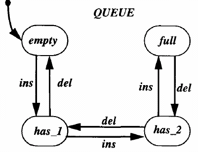
Figure-1 represents the Statechart model of a Queue. The states are represented by the rectangles with rounded corners. The state QUEUE contains four exclusive-or sub states: empty, has-1, has-2, andfull. Each state represents the number of elements in the queue. A state transition is represented by an arrow with its label representing events and conditions that enable the transition. The events may be generated externally by the environment or internally by the model.The arrival(inserti0n) and removal(de1etion) of an element from the queue is represented by the events ins and del respectively. For example, when the event ins occurs while the model is in state has-2, transition is made to state full. Note that in the given example, the model by itself does not generate these events.
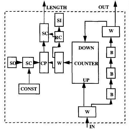
Figure-2 represents an ADEPT model for the queue. The model is comprised of various primitive blocks including source (SO) and sink (SI) for tokens, buffers (B), comparators (CP) etc. These primitive blocks are
shown connected to each other with arrows which represent the direction of flow of tokens. These arrows represent interfaces of the primitive blocks, and are also called pins in hardware parlance and ports in VHDL parlance. Tokens arriving on the pin marked IN represent arrival of elements in the queue. Tokens leave the queue through the pin marked OUT. The dotted arrow, marked LENGTH, contains tokens with information regarding number of elements in the queue, and has no token when the queue is full.
Queue example: linking statechart and ADEPT models
Given a Statechart model and an ADEPT model, where each represents a part or whole of the SUD, the next step is to identify the links between the two models.
The arrival of a token at an ADEPT module may correspond to a Statechart event that affects the Statechart portion of the simulation. In the example, the arrival of a token in the pin marked IN corresponds to the event ins in the Statechart. The removal of a token from the pin OUT corresponds to the event del in the Statechart.
Another type of linking between the two models can occur when both need to synchronize. Synchronization is required to ensure that both models have a coherent view of the simulation. For example, the Statechart model may not have the delay information associated with a specific action, and therefore simulates it in zero simulation time. The corresponding activity in ADEPT may consume some simulation time. The designer needs to identify such correlations, so that the integrated simulation environment can update the simulation time in the Statechart model. For example, the action of keeping track of number of elements in the queue has a non zero delay in ADEPT since the counter element is updated, whereas the Statechart counterpart of performing a state transition has no delay involved, as it involves a transition from one state
to the other. This implies that any simulation activity in the Statechart should be suspended till the counter in ADEPT has been updated. The third kind of correlation occurs when the designer asserts that two simulation activities must match. The models must be continuously monitored to validate the assertion. For example, having no token in the LENGTH pin implies that the Statechart model must be in the state named “full”.
Queue example: cosimulation
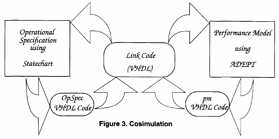
Once the two models are integrated, the combined model is simulated and analyzed. Currently, both models are translated to VHDL. In addition, we write some code in VHDL, which we call the Link Code. Thus the integrated model that is simulated is a VHDL model with three parts: the Statechart part, the ADEPT part, and the Link Code.
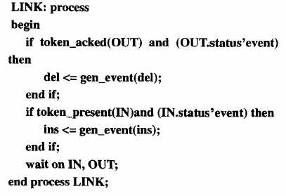
The Link Code enforces the interactions between the two models. In Figure-3, we see a portion of the link code which ensures that the events ins and del are generated for the Statechart portion of the integrated model whenever the corresponding simulation activities occur in the ADEPT portion of the integrated model.
Queue example: coanalysis
As mentioned earlier, there are two kinds of analyses, depending on whether or not the models get mapped into a common model environment. Consider the case when the models are not translated into any common model language. Both models will be analyzed independently of the other model. However, the effects of the integrated simulation will be visible to both models. For example, one can observe the effect of elements being added and removed from the queue in Statechart, while it is the ADEPT model that is generating these simulation events.
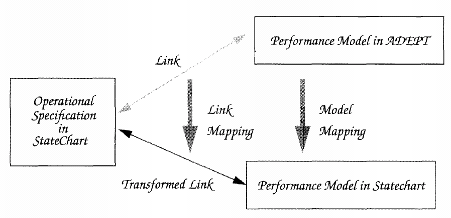
Fig-5: Coanalysis.Another possible way to analyze the two models together is by mapping one model into the other model’s environment. First consider the case when the Statechart model is mapped into the ADEPT representation. In the example of the queue, we define an ADEPT module representing the queue. The behavior of the queue is provided by the VHDL code generated by the Statechart description of the queue. This queue module can now be used in the context of larger systems that use the queue, and preliminary performance predictions can be obtained.
Yet another way to perform coanalysis is achieved by mapping the performance model into a Statechart representation as shown in Figure-5. We have developed rules to automatically transform the ADEPT representation into a Statechart representation. In addition to extending Statechart based analyses to the performance model, we would also able to animate the simulation of the ADEPT model as a result of such transformation. The automated translation of the pm in ADEPT to Statechart has not yet been implemented.
Implementing cosimulation
In order to simulate both opspec and pm in tandem, we have to make sure that the following conditions are satisfied:
- The two models run concurrently.
- The two models influence each other’s simulation only through well defined synchronization points. These synchronization points will typically represent points during simulation where, depending on the information transferred between the models, the simulation paths may diverge. Synchronization between the Statechart and the performance model must be maintained.
- The designer can assert certain conditions that must be obeyed by both performance model and the Statechart such that if the assertions are violated, the specification and the implementation are flagged as nonconforming.
When the conditions for cosimulation are met, coanalysis is enabled.
Methodology
Here we describe the design methodology enabled due to the integration of the Statechart and ADEPT models.
- A specification of the behavior of the SUD is developed using Statecharts. The specification is executable, and can be viewed as a very early prototype of the desired system. The developed model is analyzed in the Statechart domain.
- Before investing much time and effort into a detailed design, the designer will try to obtain performance predictions based on the specification alone. This is done by creating a special performance model of the SUD, which we call the specification module. The specification module has an external interface similar to the one the completed ADEPT model of the SUD is expected to have. However, the behavior of the specification module will be implemented using the Statechart specification.
The implementation of the specification module will be provided by the Statechart through the proposed “linking” mechanism. Since the ADEPT handshaking protocol involved in passing tokens among modules is not a part of the Statechart specification, one needs a clear way to relate events and conditions in the Statechart with the token passing events in the abstract module.
For example, in a performance model developed for testing a queue, one will use the specification module developed for the queue. The specification module will be an ADEPT module, with three ports, namely IN, OUT, and LENGTH in its interface. The behavior of the module is provided by the Statechart, with the designer specifying, through the linking act, how the arrival and removal of tokens on the IN and OUT port correspond to the Statechart events. The presence or absence of token on the LENGTH port is specified in a similar manner.
The specification module developed can now be used for generating preliminary results. When a test-bench is developed to test the model, we use this specification module as any other ADEPT module. Once acceptable results based solely on the specification are obtained, the designer can proceed with the detailed design for implementation of the behavior.
- Once the results obtained in step 2 seem acceptable, the system designer comes up with a possible implementation for the given specification. This design may be a complete or partial implementation for the specification. An ADEPT model is then developed for that implementation. The specification and the performance models are then linked. The linking mechanism allows one to develop the design incrementally, with the parts of the SUD that have not been designed still being simulated as Statecharts.
After cosimulation and analyses are performed and performance results are obtained, further design decisions are made, which may involve changes in the original specification.
This methodology can be applied to many combinations of discrete event simulation based specification and implementation environments. The key point to observe is that the methodology allows one to consider performance issues almost at the same time as the Specification.
Results and research in progress
Here we modeled a simple job scheduler. The SUD consisted of three priority based job queues, and three processors and a scheduler that assigned jobs from one of the queues to an available processor (See, Srinivasan, et. al., 1992). The Statechart model represented the scheduling algorithm, whereas the ADEPT model generated the simulation events of jobs arriving, and job completion times. The Statechart model alone had no information regarding the job arrival and service times, whereas the performance model alone did not model the scheduling algorithm. By virtue of integration of the two models, we were able to obtain some interesting performance predictions which otherwise would have been less accurate, since the algorithm involved would have been ignored by the ADEPT model. Some of the trade-offs we were able to investigate were job interarrival times vs. processor utilizations, queue sizes vs. job processing times etc. The main purpose of this experiment was to study the feasibility of integration.
As another example, we modeled a simple queue of a fixed size. The details of this example have been explained earlier. This example proved useful in developing the design methodology (Sarkar, 1993).
A major element of research in progress is to develop a general framework which supports the integration of the two models by identifying the possible patterns of interactions between elements in the two model spaces. We are also developing generic VHDL code that will implement each such pattern of interaction between the two models. Once generic code for implementing each pattern of interaction is available, the problem of linking reduces to identifying the elements in the respective models that comprise the link and then identifying the pattern of interaction between these elements. The link can then be implemented automatically, based on the generic code already developed for such pattern. This automation will spare the designer from having to provide the low level VHDL code. The designer thus will operate only in the Statechart and ADEPT modeling environments, without necessarily having to go into the level of VHDL, which can be seen as at a lower level of abstraction than either Statecharts or ADEPT.
Here it is developing rules to map Statechart specifications to corresponding ADEPT representations, which will be a significant step in obtaining performance predictions from specification alone, without having developed detailed performance models.
Chosen here is a system of considerable complexity, namely the IBM 802.5 token ring (Bux W., 1989). As felt, it is sufficiently complex to present a typical scenario of a real life design problem. We have developed the Statechart specification of the token ring, and are currently experimenting with the specification module as well as the performance model developed for the same. Our goal is to demonstrate the effectiveness of the complete design methodology using the token ring as an example.
Summary
In this paper, is proposed an integrated simulation and analyses of an operational specification and a performance model for a given SUD. Such integration enables a design methodology that makes specification modeling an integral part of the design process. The ability of VHDL to model digital systems at various domains and levels of abstraction is the key to the implementation of this integration. We have chosen Statecharts and ADEPT as the operational specification and performance modeling languages respectively. Feasibility of our approach has been demonstrated with simple examples. Research is in progress to develop general rules for integrating models developed in Statecharts and ADEPT respectively and to apply our design methodology to complex real life systems, such as the IBM token ring.
References
Aylor, J. H. and Waxman, R. and Johnson, B.W. and R.D.Williams,. The Integration of Performance and Functional Modeling in VHDL. In Pegormance and Fault Modeling with VHDL. Schoen, J. M., Prentice Hall, Englewood Cliffs, NJ 07632, 1992, pages 22-145.
Bux, W. Token-Ring Local-Area Networks and their Performance, Proceedings of the IEEE, Feb, 1989.
Franke, D. W. and Purvis, M. K. Hardware/Software Codesign: A Perspective. Proceedings of 13th Intemational Conference on Software Engineering, pages 344-352, May 13-16, 1991.
Habib, S. Microprogrammed (2003), ‘Architectures Specified Using Paisley’, Computer Science Department Report, 2003.
Harel, D. and Pnueli, A. and Schmidt, J. P. and Sherman, R. On the Formal Semantics of Statecharts. IEEE Press, pages 54-64, July, 1987.
IEEE,. IEEE Standard VHDL Language Reference Manual, IEEE Inc., NY, 1988.
Jensen, K. Colored Petri Nets: A High Level Language for System Design and Analysis. High-level Petri Nets: Theory and Application:44-119.
Kronlof, K. Method Integration: Concepts and Case Studies, Wiley Series in Software Based Systems, Wiley, 1993.
Opdahl, A. L. and Solvberg, A. A Framework for Performance Engineering during Information System Development. Advanced Information Systems Engineering (Advanced Information Systems Engineering CAiSE ‘92, Manchester; UK):65-87, 1992 proceedings.
Peterson, J. L. Petri Net Theory and the Modeling of Systems, Prentice Hall, Englewood Cliffs, N.J., 1981.
Sarkar A, Waxman R & James P (1994), ‘System Design Utilizing Integrated Specification and Performance Models’, Computer Science Electrical Engineering Computer Science, University of Virginia, Charlottesville, VA 22903, 2003.
Schefstorm, D and van den Broek, G. Tool Integruti0n:Environments and Frameworks. Wiley Series in Software Based Systems, Wiley, 1993.
Srinivasan, S. and Sarkar, A. and Waxman, R. and Johnson, B. W. Integrating Operational Specification and Performance Modeling. Fa11’92 VHDL International Users’ Conference, Washington DC, 10/18/92.
Sarkar, A. Integration of Operational Specification and Performance Modeling for System Design. Ph.D. Thesis Proposal 1993.