Abstract
The transportation of oil and gas from offshore fields provides a significant challenge to the oil and gas industry because of the problems associated with the formation of gas hydrates within the piping system used to transport the fluids. Here, gas hydrates are crystalline solids that form when a combination of the right conditions of pressure and temperature in the presence of water and gas is attained within the piping system. Gas hydrates formation within the piping system is costly and adversarial to the production and transportation of oil and gas to subsurface facilities. This study will focus on the formation of gas hydrates, problems associated with transportation, multiphase oil and gas transportation, flow assurance problems associated with the formation of gas hydrates, and the methods for solving the problems associated with gas hydrate formation. An in-depth study into the conditions under which gas hydrates form and the accompanying compounds using a mathematical model to determine boundary conditions provides the basis for studying the techniques for inhibiting the formation of gas hydrates. The use of kinetic inhibitors which work by being injected into the wellheads with recommendations is one example with further studies recommended on biological hydrate inhibitors.
Introduction
Inhibiting gas hydrate formation during multiphase hydrocarbon transportation from subsurface oilfields to surface facilities is critical to avoid flow assurance problems based on the chemistry of the substances. In the context of the oil and gas industry, many challenges are experienced because an increasing number of the sources of oil and gas are offshore and in cold and deep waters. The consequence of mining oil and gas and transporting the products offshore requires longer subsea tiebacks to the target processing facilities. Among the most serious problems associated with the transportation of oil and gas is the formation of gas hydrates, which come in the form of solids wax and asphaltenes and plug the pipe and cause a serious flow assurance problem. In addition, the gas hydrates’ formation process is quite rapid, causing a further challenge in the transportation of the oil and gas, especially from deep-sea wells (Bai & Bai 2005, p.23).
The chemistry of gas hydrates shows that they are crystalline substances formed due to hydrogen bonding with water molecules in a lattice structure whose stability is due to the encapsulation of a guest molecule such as methane. Hydrates require the presence of water and gas with the right combination of low temperatures and high pressure, in the right quantities to be formed. The cause for the flow problems associated with hydrate formation is because of the right combination of conditions that arise and prevail during the transportation phase (Durham, Stern & Akirby 2003, p.4). To address the problems associated with the flow of oil and gas, the current study will focus on the chemistry of the formation of hydrates, flow assurance problems related to the gas hydrate formation, and the method on solving the gas hydrate formation related problems to the oil and gas production industry. The solution to the problems associated with the formation of gas hydrates during the transportation process is addressed based on thermodynamics for subsea pipes.
Background and Context
Gas hydrates form when the right conditions of water, gas, pressure, and temperatures prevail during the transportation process. The case with the formation of gas hydrates during the transportation phases provides critical challenges for the oil and gas industry particularly because the sourcing of oil and gas is becoming far from the inland regions and deep into the sea. Once the exploitation of oil and gas has been done, the transportation of the substances offshore because of the chemical and physical properties of the substances presents challenges that require their inhibition to ensure effective delivery of the compounds. In that context, the current study will examine the formation of gas hydrates, structure, and physical properties, the effect of the properties on the flow of gas and oil, and inhibiting of the formation of the hydrates to address the flow assurance issue. Evidence from the operations in the oil and gas industry shows that plugging can lead to costly operations and at times might lead to shutting down of operations within the industry. It has been shown that hydrates are a problem in the industry, where significant costs are incurred in preventing the formation of hydrates. Hydrates are an industry-wide problem for good drilling, for pipelines, and especially when using water-based drilling and transportation of oil and gas.
Statement of the Problem
The formation impairs the operational efficiency during multiphase transportation of oil and gas to surface facilities, which requires inhibition solutions to improve the operational efficiency when being transported.
Research Objectives
- To study the formation of gas hydrates
- Study the transportation of oil and gas
- study the flow assurance problem due to gas hydrate formation
- study the methods for inhibiting gas hydrate formation
Literature Review
Forming of gas hydrates
In the context of this study, gas hydrates form due to the contact established between water molecules at elevated pressures and within a temperature range that lies above and below the freezing point of water. Gas hydrates that form are crystalline in nature and have mechanical properties that are close to the mechanical properties of ice, and have a phase equilibrium that is determined by the guest molecules, which are caged in the water molecules. In this case, the thermal properties of gas hydrates are determined by the hydrogen-bonded crystals that lie within the range of the guest molecules and which fit exactly into the size of the molecules. In many cases, the substances that make up the composition of the gas hydrates include “methane, ethane, propane, isobutane, normal butane, nitrogen, carbon dioxide, and hydrogen sulfide” (Servio & Englezos 2002, p.5).
An example is the constitution molecules, which include ethyl cyclohexane with an equivalent size of <0.9 nm and argon with a <0.35 nm to form gas hydrates. That qualifies the argument that gas hydrates form from a combination of different components which might be in the vicinity of water and the guest molecules. Research shows that hydrates have a concentrated composition of hydrocarbons and which exist in hydrated forms (York & Firoozabadi 2009, p.4). Gas hydrates that exist are geologically distributed and their formation was influenced by the prevailing temperatures and other conditions. Research has shown that gas hydrates formation is controlled by the underlying formation temperature, gas chemistry of the coupling elements, pore-pressure, availability of water and gas, gas chemistry, pore-water salinity, and the migration pathways that gas and water followed during the formation process. That is in addition to the presence of reservoir rocks and appropriate seals. While all the above-mentioned factors contributed to the formation of one or another type of gas hydrates, the following discussion is on the formation of gas hydrates based on the geologic processes.
Physical properties
Gas hydrates are formed into solid materials which have densities that are higher than the densities of the hydrocarbon components which are constituent mixtures in natural gas (Chen 2004, p.4). Studies have shown the gas hydrates to possess mechanical properties similar to that of ice with thermal properties of 0.393 Wm-1K-1 at 215.15 K. when compared with ice; the thermal properties of gas hydrates are five times less than the thermal properties of ice which are 2.33 Wm-1K-1. Gas hydrates have a lower thermal conductivity compared with ice (Durham, Stern & Akirby 2003, p.45).
Geologic formation
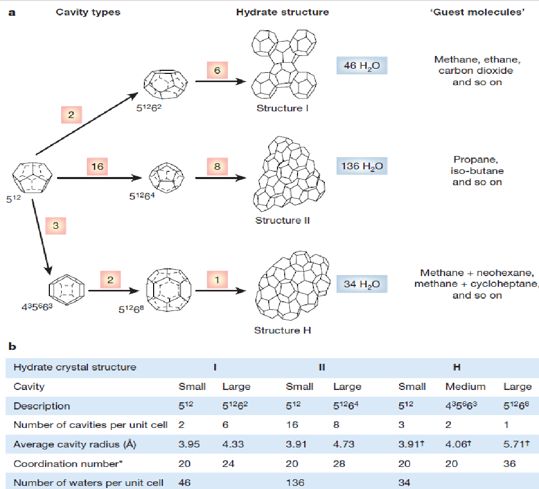
It is generally known that gas hydrates exist in an environment with limited temperature and pressure conditions. The formation structure in which the gas hydrates exist makes it easy to calculate the thickness and depth where the gas hydrates reside. It is possible to illustrate as shown in the figure below (figure 1), the effects of pore pressure, temperature, and the composition of the gas have on the depth and thickness of the gas hydrate that has been formed. In this case, the formation of the gas hydrates undergoes different phases in the formation process. Among the factors considered in this phase, diagrams are the mean annual surface temperature which is taken to be -10Co, making the base of the permafrost to be 00C. However, different temperature profiles affect the prevailing characteristics of the permafrost. The permafrost reactions are in this case isotherms. Here, there are three different geothermal ingredients that affect the temperature of the permafrost. Among these are the two gas stability hydrate curves which are representative of each of the gas chemistries that define different composition makeups of the substances. Observations show that the 100% presence of methane is evident in the high stability curve, with the other curve showing 98% methane, 1.5% ethane, and the rest, 0.5% being propane. As already mentioned, the formation process is influenced by among many other factors, the pore-pressure gradient. An interesting observation is a zone that represents the region of high hydrate stability, which occurs between the regions that represent geothermal and gas hydrate stability as shown in the intersections within the diagram. A typical example is shown in figure 1B.
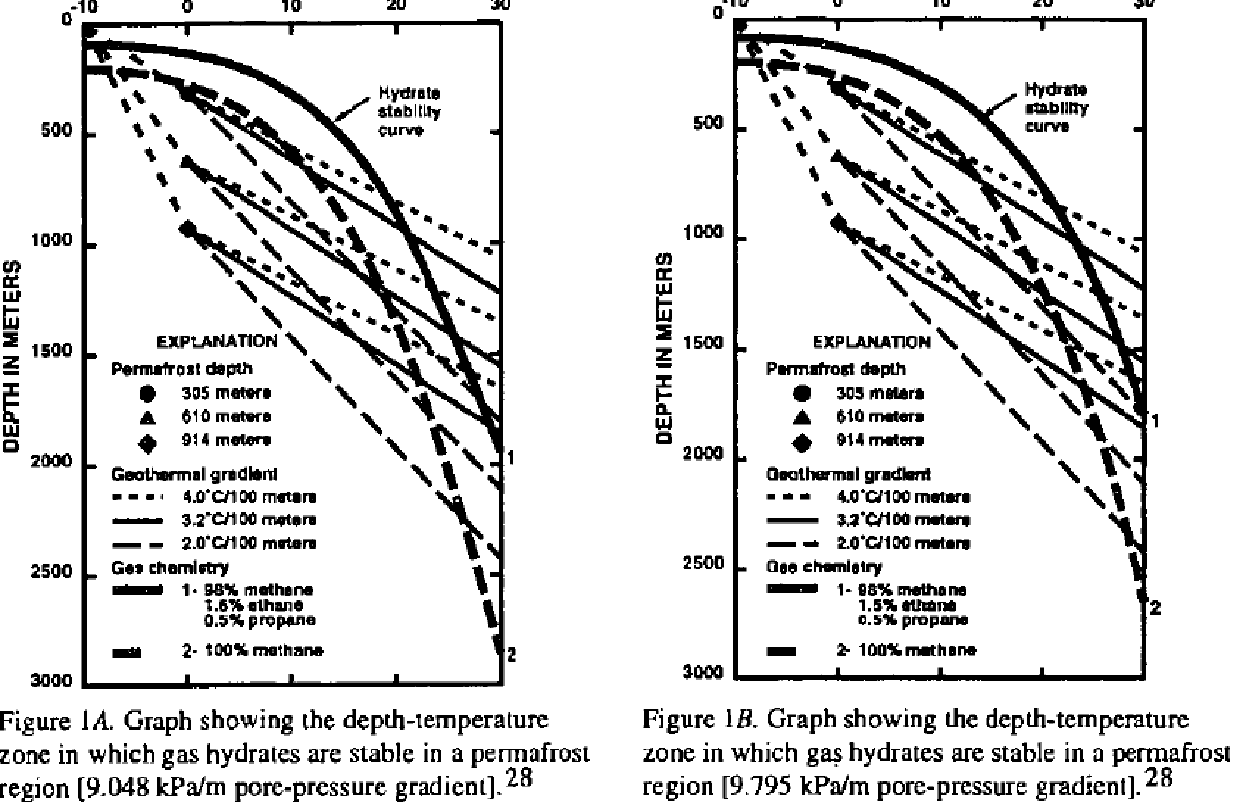
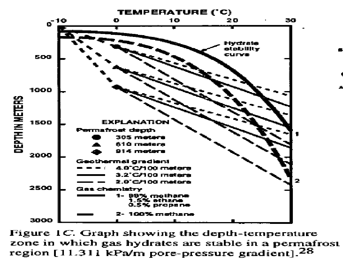
A typical example includes where the formation of the gas hydrate is in porous rock.
Structure
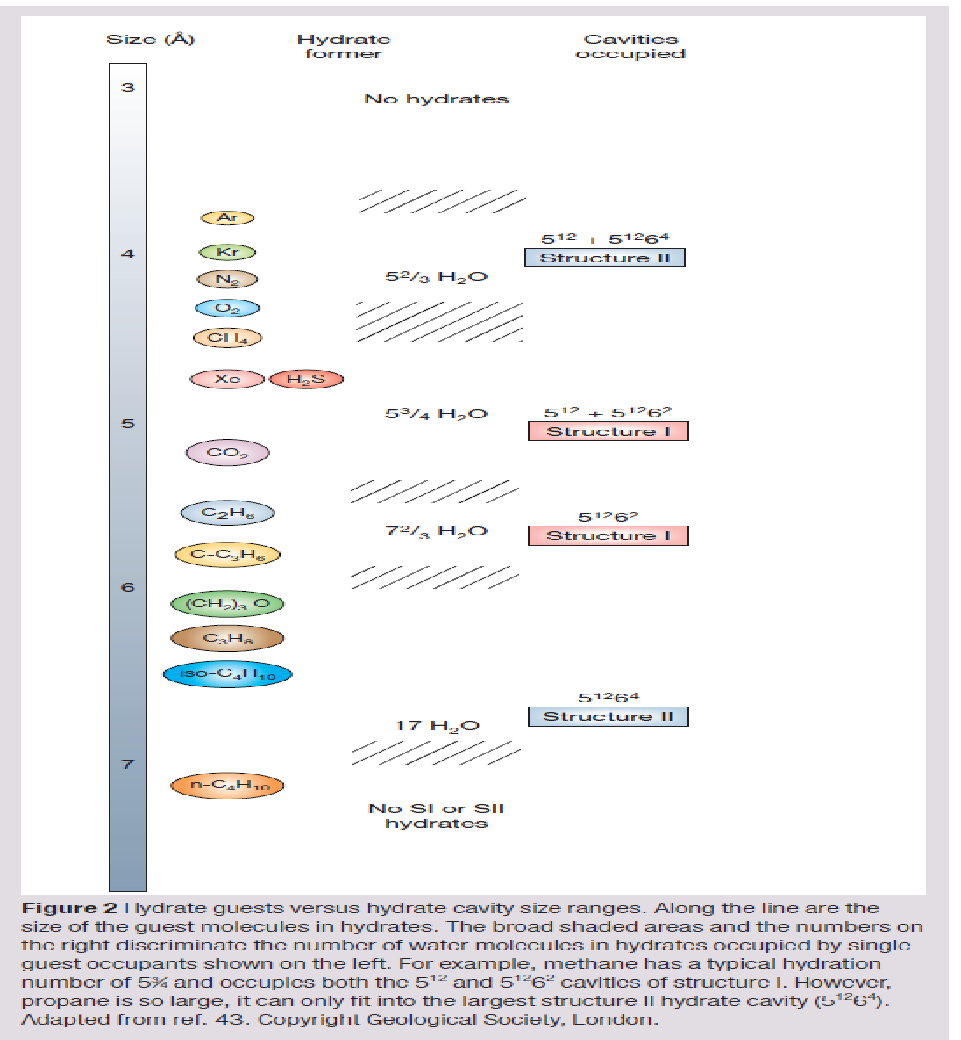
A gas hydrate is a solid crystalline structure with water and gas as the building blocks. Gas hydrates are defined by a variable, nonstoichiometric composition whose properties are influenced by the conditions underlying the formation process with the constituent gas falling within a maximum value that is never exceeded. The link between the guest and the host substance is that of the hosting substance with steric forces as opposed to chemical substances that bind the two substances together. The gas hydrate consists of clathrate which hosts a guest substance in gaps found in the host substance. Gas hydrates physically resemble the crystalline structure of ice. In context, gas hydrates form when the guest molecules that are very small, in the range of <0.9 nm, which might include substances such as carbon dioxide or methane, establish contact at ambient temperatures of less than 300 k and pressures that are moderately applied on the substances in the range of0.6 MPa, on the scale and level of the molecular dimensions. In this case, the molecules are singularly engaging in cavities that are hydrogen-bonded water molecules in the hydrates that are non-stoichiometric in nature. The guest molecules create forces of repulsion which cause different sized cages in cages in the water molecules to be propped open to produce different types of crystalline structures. Figure 1 below provides a detailed mapping of the three different types of crystalline structures that result from the impact of the forces of repulsion between the guest molecules and the water molecules.
Studies show that the crystalline structures classified under the cubic structure 1 are predominant in the earth’s crust and the natural environment with a small percentage of guest molecules occurring in the range of 0.4-0.55 nm. The second cubic structure occurs in the range of 0.6 and 0.7 nm and predominantly occurs in the man-made environment. In this case, the molecules occur in a mixture of sizes varying between 0.8 and 0.9 nm. On the other hand, the smallest molecules occur in the form of O2 molecules among other types of molecules from different substances and occur in sizes of 0.4 nm. Research has shown that most of the applications concentrate more on the structure I and structure II substances with structure H hydrates forming the most significant form in most analogous occurrences.
Investigations show that most of the molecules have only one guest molecule within any one cage. However, if conditions are varied by altering and increasing factors such as the pressure and temperatures of exposure, the structures get changed significantly. Typical examples indicate that if the pressure of exposure to the molecules is increased, there is the likelihood of developing a multi-cage occupancy that is characterized by small guests that include hydrogen, and some noble gases. Examples include where hydrogen has been shown to form hydrates when subjected to very high pressures. It is possible in this case to consider the guests the small guests and the multiple occupancies as an aberration (Lachance, Sloan & Koh 2008, p. 9). Findings indicate that when hydrate cavities are fully filled, then the three crystal types show similar concentrations of the components that make up the structures. That includes 85 mol% of water and 15 mol% of the guest substance. With the resulting characteristics of the molecules, the likely formation of the hydrates is likely to occur at the interface between the bulk guest and the aqueous phases. In this case, the hydrate components have high concentrations and significantly exceed any mutual fluid solubility. Once the substances have been formed, the interface established on the film provides a barrier reducing any further contact of the bulk-fluid phases. In this case, there is a need for the fluid surface renewal to continue with the clathrate formation phases. To provide a clear and comprehensive understanding of the hydrates, it is crucial to conduct a guest to cage ratio study (Taylor, Miller, Koh & Sloan 2007, p.60). That is in addition to providing a full comprehension of the thermodynamic properties of the structures in the first point of approximation.
Simple hydrate guests
The simple hydrate guests as illustrated in figure 2 below.
The Multiphase Oil and Gas Transportation-phase technology
Since production has moved on to new environments that are hostile, it has compelled the need to use the multiphase transportation techniques to achieve higher operational efficiencies and address the challenges that come with less effective transportation methods. In this case, the production and transportation scenarios vary because of the need for improved efficiency. According to study findings indicate that the, production and transportation process based on a transient multiphase flow model (Mokhatab, Wilkens & Leontaritis 2007, p.8). Among the techniques used on transient multiphase transportation, phases are discussed below.
Line Sizing
It is crucial to select the right size of pipe to make the multiphase transportation of gas and oil effective and reliable. Studies show that is important to select the right size based on the available pressure to transport effectively the anticipated flow. At this point, it is important to take into due consideration based on the production rates, the pressure drop constraints, and flowing well head pressures that lie within the envelope of operability. In this case, varying the line size provides clear guidelines on establishing the appropriate boundaries in this case, a number of models that include steady-state simulations provide near accurate data on the size of pipe to use depending on the prevailing conditions.
Typical examples of line sizing and the effects of sizing the transportation pipe are tabulated in table 1 below.
Table 1, RHM Fluid Power INC. n.d.
As shown in the above table, linen sizing has a direct impact on the velocity of the fluid flowing in a pipe of a given size. According to the table provided above, the line size and the size of the pipe used in the transportation of the fluid are critical in optimizing the performance of the transportation system. That is in addition to making the best combination of requirements to determine the best to reduce friction and system overheating. Studies indicate that by selecting the right size of pipe, the cost of the transportation system is minimized accordingly. In this case, the length of the pipe and the pressure associated with the source, which is the actuator is calculated appropriately to ensure the pressure drops do not adversely affect the transportation of the fluid within the pipe. Therefore the right size and length of the pipe should be integrated with selecting the transportation pipes to provide effective fluid flow.
Typically, a multiphase flow network consists of the source, the wells, and the destination installations for processing the inputs. In practice, offshore oil fields consist of marginal fields defined by small accumulations of hydrocarbons and long sea tiebacks, with deep water fields occurring in the range of over 1000 meters. A two-phase flow regime is illustrated in figure 3 below.
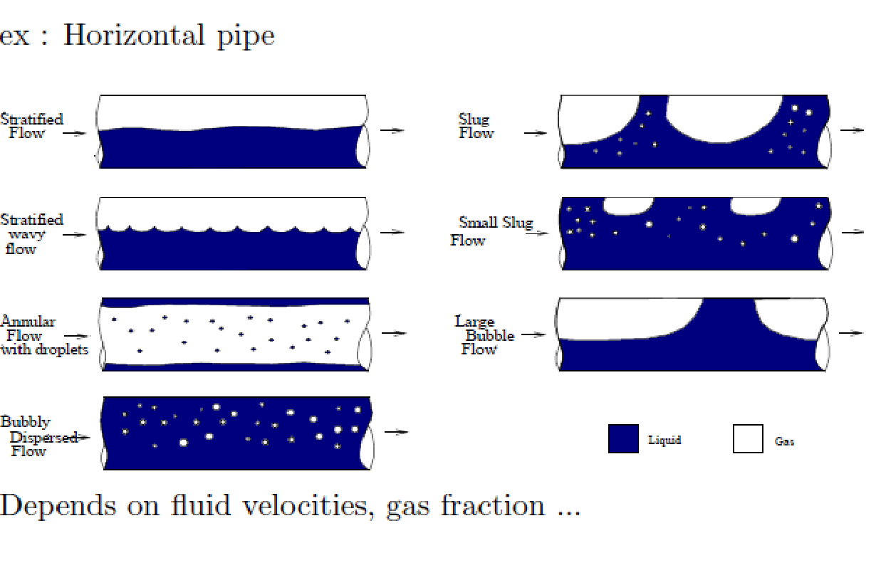
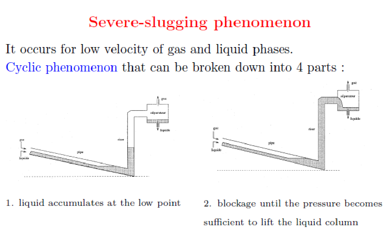
A combination of big differences in flow gravity, gas density distribution due to pressure changes, different elevations of the pipe, which includes the pipe lying in the sea bed, and the operating terrain, provides an environment for the formation of slug blockage as shown in figure 4 below.
In the above case, the fluid flow is based on comprehensible liquid and gas, and the transfer of mass between the phases assuming the phases occur under thermodynamic equilibrium conditions. The flow can be modeled mathematically as a drift flux model.
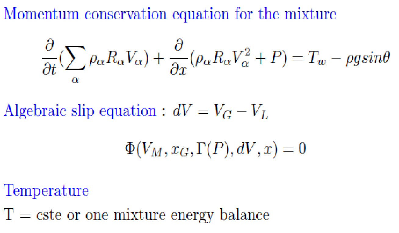
In the above DFM, then nonlinear conservation laws of hyperbolic systems and isothermal gas-liquid flow are significant characteristics of the model as shown below.
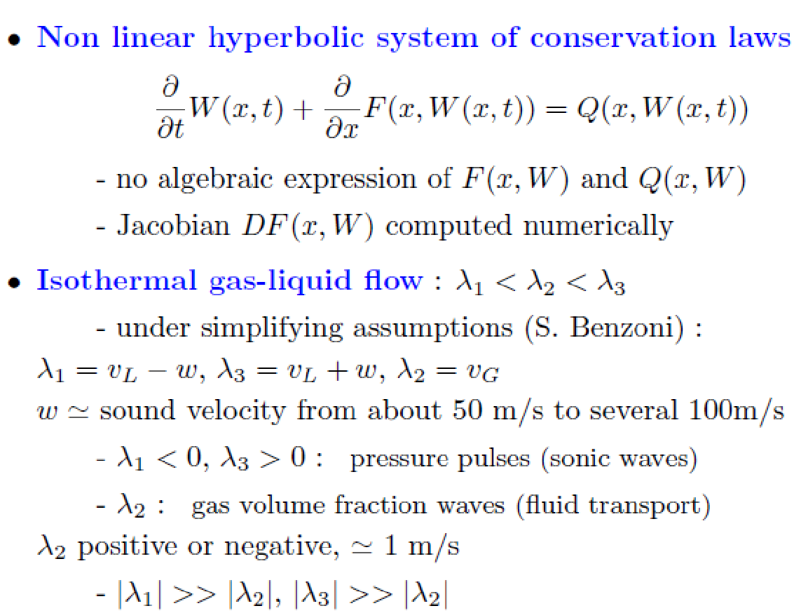
In the above model, the boundary conditions are illustrated mathematically as shown below.
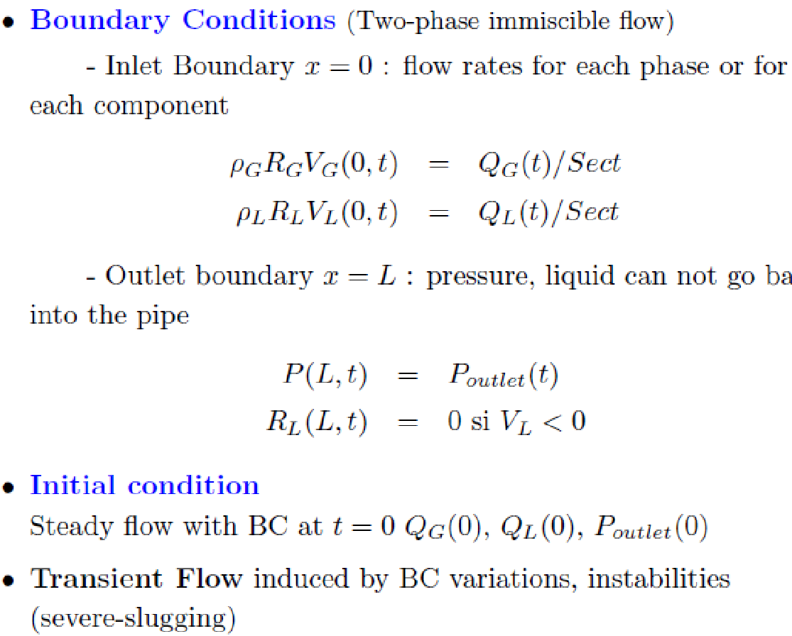
The mathematical models illustrate the prevailing conditions when doing offshore transportation of oil and gas through piping infrastructure that allows the flow of the fluids from source to destination.
The flow assurance problems related to the gas hydrate formation
Flow assurance provides a controlled and reliable flow of oil and gas to the point of sale. The flow assurance problem is multidisciplinary and requires an integration of scientific knowledge to deal with the technical problems to provide efficient and safe flow assurance (Sloan & Bloys 2000, p.12).
The flow assurance problem is evident in the line and unpacked methods. Here, the flow assurance problem associated with the line assurance related to the gas hydrate formation is influenced by the formation of a water-in-oil emulsion. In this case, water plays a critical role in the formation of the agglomerate of the particles resulting from the hydrate that flows within the pipe. The formation of the hydrate molecules forms hydrates shells which are found to be predominant on the outside of the water molecules. During the transportation process, water molecules convert, when subjected to high pressures, to hydrate molecule and undergoes through a number of stages that include initial formation, the thickening of films, and bulk filling of the hydrates (Wu, Wang & Liu 2007, p.5).
On the other hand, additional problems incurred in the transportation of the substances are in the formation of the crystalline substance that is wax-like when flowing within the piping used for the transportation of the substances. The wax-like substance contributes to the clogging experienced in the lining within the pipes during the hydrating fluid flow process. The bromine hydrate structure-related flow problem has been successfully solved because researchers have taken time to examine the 16 different crystals with different hydration numbers and morphologies. One of the structures that have had sufficient attention is the tetragonal form, done by Jeffrey. In context, a detailed study using the Xe NMR spectrum observations for xenon that had been found trapped inside the cages with provided excellent sites for the trapping of CO2, led to one of the solutions to the flow problem related to coagulation. One of the focal points of interest in the flow assurance of the gas hydrates is related to hydrate blockage.
Hydrate focus on flow assurance problem
To establish the flow assurance problem due to the formation of the gas hydrates, it is important to examine in detail the formation and structure of the gas hydrate in relation to the physical behavior of the gas during the transportation period.
Research has shown that gas hydrates can form anywhere along a pipe when the conditions within the formation environment are conducive. In this case, the formation of the hydrates is due to the presence of water and gaseous molecules at the right temperatures. Here, gas hydrates are defined into solid crystalline compounds with a structure consisting of guest molecules entrapped in a cage, but without any chemical bond being developed. The gas hydrate formed in this setting is due to the hydrogen bonds which cause the water molecules to form regular alignments and orientations. Here, the presence of additional foreign compounds causes the molecules which have been aligned to precipitate and stabilize into guest and host molecules. The underlying reason for the stability that is established within the molecules is due to Vanderwaal’s force, which is in addition to the fact that no bonding exists between the host and guest molecules. That makes the guest molecules have the freedom to move about the cage that is formed by the host molecules. Research has shown that no hydrate molecules exist on their own but exist due to the stability provided by the weak intermolecular forces of attraction between the guest molecules and the water molecules. It is critical to add that the hydrate molecules, besides forming due to the presence of water, appropriate pressure, and guest molecules, require other conditions which include high pressure and low temperature, the presence of hydrates, and water in sufficient amounts. Once such conditions have been fulfilled, it is possible for the formation of hydrates to occur anywhere within the fluid transportation pipe (Zhao & Ding 2004, p.10).
No prior indicator provided an early warning of the possible occurrence of a hydrate formation. However, the most effective method of detecting the formation of hydrates is a sudden drop in pressure which is due to an abrupt flow blockage. It is in rare instances that hydrates form within the well because the temperatures are high and do not favor the formation of the gas hydrate.
To determine the formation of gas hydrates in a pipe, it is important to examine pigging returns in a pig receiver discharge, variations in fluid rates and their compositions at the separator, and a decrease in the flow rate accompanied by a drop in pressure and acoustic detection using a sand monitoring instrument.
The method of solving the gas hydrate formation-related problems
Inhibition of Subsea pipelines
The problem of gas hydrate formation can be addressed based on a number of approaches. The natural gas hydrate inhibition for subsea piping is done by chemically inhibiting the formation of the gas hydrates using chemicals that prevent plugging, when the startup and shut down conditions are attained. Here, the procedure includes dehydration of water removal and wet gas at the onshore and offshore facilities by ensuring that the operating temperatures are confined to avoid the temperatures that favor the formation of gas hydrates by ensuring the operating pressures are out of bounds of the pressure that favors the formation of gas hydrates. In addition, injecting either thermodynamic or kinetic inhibitors at the wellhead provides cost-effective methods of recovering the inhibitor. In this case, the most popular chemical in use was glycol and methanol, which form hydrogen bonds with the molecules of water that are present to prevent the possibility of forming cage molecules that act as guest molecules and create the necessary conditions for the formation of gas hydrates. Another method is to use glycol based solutions. On the other hand, the use of low dosage inhibitors for pipes used in the subsea sections that constitute kinetic inhibitors has been suggested to be one of the emerging solutions for subsea piping. Kinetic inhibitors work by lowering the rate at which gas. In this case, the kinetic inhibitors provide the solutions by nucleation rate of hydrate inhibition, preventing in the long term the nucleus from acquiring the critical mass. In this case, kinetic polymeric inhibitors are used with the surface-active agents because they prevent emulsification between the gas and water molecules. Other methods that have been proven include the use of biological hydrate inhibitors which fall under the category of anti-freeze proteins.
Methodology
The current research was a qualitative study of the literature review of secondary sources detailing the formation of gas hydrates, transportation of gas hydrates, flow assurance problems, and the methods used to address the problems associated with the formation of gas hydrates. A desktop literature review of different authors detailing the structure and formation of gas hydrates based on a mathematical fluid flow model in this case gas flow thermodynamics and prevailing boundary conditions and the drift due to the flow of the fluid in piping for transporting the fluids formed the literature to be reviewed. The study continued with an evaluation of the problems and methods of transporting the fluids provided further proposed areas of study.
Conclusion
In conclusion, because an increasing amount of oil and gas exploration is based in offshore fields, there is a need to integrate gas hydrate formation solutions that are experienced during the transportation of gas and oil from the source to the destination. The form of solids wax and asphaltenes and plugs the pipe escalates the problem associated with the gas hydrate formation. In this case, the flow-related problems to gas hydrate formation have been due to the favorable conditions, of a combination of the right pressure and temperature conditions in the presence of water and gas molecules that cage the formation. In this case, the gas hydrates are crystalline substances with mechanical properties similar to that of ice. During the transportation of gas and oil, there is the likelihood of the gas hydrate forming at the interface between the bulk guest and the aqueous phases, which creates a barrier leading to the clathrate formation with its blocking properties. Transporting oil and gas to the offshore storage facilities can only be done using techniques such as calculating the right size of piping in relation to the pressure and other physical characteristics that directly influence the formation of gas hydrates. The potential for the formation of gas hydrates can be reduced based on mathematical models when selecting the piping to be used in transporting oil and gas and techniques that include kinetic inhibitions to overcome the problem.
Evaluation
An evaluation of the current work and methods of inhibiting gas hydrate formation to effective and cost-effective flow within the piping framework provides a number of solutions that have been applied in the industry. In this case, the cost associated with the gas hydrate formation and the effects compel solutions to address the problem. One such is the use of thermal methods. In this case, the use of glycol brings to attention the cost implications because the method is expensive. However, the use of kinetic inhibitors has proven cost-effective and under extreme conditions, the kinetic inhibitors do not perform well. Extreme undersea conditions require the use of Anti Agglomerant and biological hydrate inhibitors.
Future work
The is a need to conduct further studies on the thermal techniques of inhibiting gas hydrate formation during the transportation of gas and oil from offshore facilities. In addition, there is also a need to conduct further studies on the feasibility in terms of cost and performance of using biological hydrate inhibitors in deep-sea conditions.
References
Chen G L 2004, ‘Natural Gas Industry’, Journal, vol 24, no. 8, p. 89.
Bai, Y & Bai, Q 2005, Subsea Pipelines and Risers, Elsevier Science Ltd.
Durham, W B, Stern, L & AKirby. SH 2003, Ductile flow of methane hydrate, Natl. Res. Council Canada, Canada, pp. 373-380.
Lachance, J W, Sloan, E D & Koh, C A 2008, ‘Effect of hydrate formation/dissociation on emulsion stability using DSC and visual techniques’, Chem. Eng. Sci. vol. 63, p. 3942.
Mokhatab, S, Wilkens, R J & Leontaritis, K.J 2007, ‘Energy Sources, Part A’ Recovery, Utilization and Environmental Effects, vol 29, pp. 39-45.
Servio, P & Englezos, P 2002, Measurement of dissolved methane in water in equilibrium with its hydrate. Journal of Chem, Eng, 47, 87–90.
Sloan, E D & Bloys, J 2000, ‘Ben Hydrate Engineering’, Society of Petroleum Engineers Inc., Richardson, TX, USA.
Taylor, C J, Miller, K T, Koh, C A. & Sloan, E D 2007, Macroscopic Investigation of Hydrate Film Growth at the Hydrocarbon/Water Interface. Chem. Eng. Science, vol. pp. 62, 6524.
Wu, M, Wang, S & Liu, H 2007, ‘A Study on Inhibitors for the Prevention of Hydrate Formation in Gas Transmission Pipeline’, Journal of Natural Gas Chemistry, vol 16, no 81, p. 85.
York, J. D & Firoozabadi, A 2009, ‘Effect of brine on hydrate antiagglomeration’, Energy Fuels, vol. 23, pp. 2937–2946.
Zhao Y, Ding J 2004, ‘Natural Gas Industry’, Journal of Natural Gas Chemistry, vol. 24, no. 12, p. 132