Maintenance Management of Modern High Thrust Aircraft to overcome Volcanic Ash Effects
It is necessary to optimize the aircraft’s uptime and maintain its engine. For instance, a system for verifying an aircraft engine on the ground ought to be developed, and vibration measurements done according to the procedures specified in the manual provided by the manufacturers of that engine. Furthermore, a tachograph can measure vibrating signals. The user interface in identifying the engine directs the technician, as well comparing the threshold levels and monitoring the signals that will be useful in measurement confirmation (Morris 1998).
Moreover, the technician should use the user interface while storing the signal in its respective database as well as use it in producing a service report, in which there is a clear illustration of the results. For further critique, it is necessary for the technician to send directly this report to the manufacturers of the aircraft engine. Actually, vibration checks on particular aircraft engines have their on the specifications, which may encompass the following:
- An alarm the moment there is an occurrence of a low level.
- An alarm the moment the limitation levels are out of range.
- Verification of the levels of vibration should be with respect to two tachometer signals, that is, a signal from the engine’s power turbine and a signal from gas generator.
- TEDS automatically identify sensitivity and accelerometer.
Thus, it is beneficial to maintain an aircraft engine; the main requirements are how the engine has been set up. Currently, there exists a wider range of aircraft engines, such as Arriel engines and Makila engines. Therefore, while examining maintenance wise solution to an aircraft engine, this paper will concentrate on inspection and optimization.
Inspection
An airplane ought not to be flown the moment someone suspects that it has a problem, such as a stuck valve. This is because the pilot of that airplane is likely to experience an abrupt loss of power during take-off and as such, a number of engine parts, like push rods or camshafts could be the cause when they are out of order. In order to avoid this, it is necessary to inspect an aircraft engine. Stuck valves may cause periodic misses and thus there is an effect of bumping throughout the aircraft frame at take-off. Both the intake valves and the exhaust valve may have stuck; a problem that is due to build-ups of carbon deposits in the valve-guides. In fact, this problem occurs with hot aircraft engines or those operated in conditions with high heat. As mentioned before, a stuck valve could lead to detrimental effects such as power loss and faults in internal components. (Wallace 2001).
Assessment of Damage
Often, defects on an aircraft engine will occur on the engine’s inner surface. However, the majority of aeroengine borescopes are only capable of detecting those damages but are incapable of determining the extent of those damages. In order to assess the extent of damage to an aircraft engine to give the relevant maintenance wise solutions, we ought to employ a borescope assessment ES (expert system) that is novel. While using the ES, it is possible to fix images damaged due to archetypal and maintaining the standards required. Nevertheless, a support vectors machine that is based on a binary tree can be used as a machine for reasoning, so as to acquire a case knowledge and then implement a logical reasoning that facilitates the learning capability, precision and inference velocity of the ES. (Dalton 1999). Supremely, a borescope inspects an aircraft engine’s inner surface and then display the images to illustrate the probable damaging impacts of the flight activities. In some cases, those images can reveal the notion that a significant damage to the engine of an aircraft is possible by short-term flying. Overheating can be due to a continued operation and this is a threat to both a pilot and an aircraft (Bendict 1992).
Types of Tests
During the maintenance of an aircraft engine, it is vital to inspect the damage and then scrutinize the degree of the needed repair. The major economical way of inspecting an aircraft engine is by using NDT (non-destructive testing). NDT is of great importance because of its ability to detect cracks that are invisible by the naked human eye (Hunecke 1997). In order to ensure that the aircraft is free of defects and guarantee that the inspection quality and dependability is of high quality, the following types of NDT tests are applicable in magnetic-particle test, sonic effects, use of eddy currents, die-penetrant and Infrared Thermography tests.
Liquid Penetrant
This method is one of the oldest NDT methods and is of extensive use in maintaining an aircraft engine. As Chant (1998, p.22) puts it, “Liquid penetrant testing can be defined as a physical & chemical non-destructive procedure designed to detect & expose surface connected discontinuities in ‘nonporous’ engineering materials.” The rudimentary aim of this type of testing is to escalate the contrast between a background and its discontinuity. This method proves to be highly dependable in terms of visibility of cracks and seams due to welding. This testing method is mainly applies in detecting structural damages or surfaces in the entire aircraft material (Little 1997).
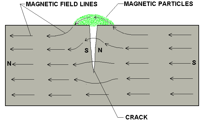
Magnetic Particle
This type of testing is sensitive for sub-surface discontinuation and surface-breaking in materials that are Ferro-magnetic. Furthermore, this technique of testing, as Hetzel (1995, p. 113) observes, is on the basis that, “magnetic flux in a magnetized object is locally distorted by the presence of discontinuity.” This occurrence is flux-leakage. As such, there are three basic operations in this test, that is: using longitudinal magnetisation or circular magnetisation to establish a magnetic flux that is suitable; application of magnetic particles in a liquid-suspension; and examining the test under apposite conditions of light for assessment and interpretation of the indications (Hewitt 2000).
Eddy Current
Corrosion due to stress and fatigue are the primary causes of surface cracks/wear. Idyllically, these types of tests have a high sensitivity degree As Richards (1998, p.43) assert, Eddy currents can be defined as, “electrical currents induced in a conductor of electricity by reaction with alternating magnetic field.” Inspecting a system of Eddy current entails the following five methods: Read out, oscillator, absolute test coil, circuits’ bridges and those for signal processing. This type of testing is mainly useful in detecting sub-surface and surface defects, and aircraft structures corrosions (Nahum 1999).
Ultrasonic
This testing type allows visibility of small flaws thus showing both the size and the location of a defect. In cases whereby both of the surfaces are parallel, then we may employ ultrasonic tests to measure thickness. The ultrasonic tests result normally relies on the following facets: the condition of the surface; acoustic-impedance; the direction; and grain size. Supremely, these tests operate on the principle of reflected and transmitted sound wave. The techniques used in carrying out ultrasonic tests are Pulse-echo (Reflection) technique and Transmission technique (Lopez 1995).
Radiography
A radiograph is, “a photographic record produced by the passage of electromagnetic radiation such as x-rays or gamma rays through an object onto a film” (Time Life Books 2000, p.225). Concerning the absorption capability, as well the penetration of x-radiation, Maurer (2000) asserted that, the majority of an aeroplane’s non-metallic parts have a likelihood of inspection to determine breakage; porosity; crashed-core and the entrapment of water. In addition, radiography is important in locating dis-continuities in the formulated structural assemblies, encompassing: fittings that are loose; deterioration; debris and disparities in thickness.
Visual
This testing type is of high significance because its facets may encompass the following: are cheap; it is uncomplicated; and is not difficult to apply. The rudimentary principle employed in this test aims at illuminating the test-specimen and assessing the specimen by use of the eye. Visual testing is applicable in magnification of the imperfections that are invisible by the naked eye; helping in inspecting imperfections; and allowing visual-checks. Structural damage assessed using this method. Conspicuously, it is important in monitoring the components of the engine, like blades combustion and nozzles without necessarily opening the aircraft engine (Mellett 1997).
Infrared Thermography
This type of testing is based on the notion that, “heat flow in materials is altered by the presence of some types of anomalies” (Boyne 1997, p.47).The infrared rays are best in detecting voids in engineering structures and contaminations in liquids. Others in the same category will be inclusions together with debonds.
Equipment needed
The main equipment needed are:
- Inspections include a borescope assessment expert system and Support Vectors Machine. The end of the borescope has illumination to enhance viewing. Magnification lenses help to make any possible crack more visible to the person carrying out the inspection.
- Aircraft Liquid penetrant testing include: Spray cans (Aerosol); tanks that are deep (for the penetrant); emulsifier; a wash-area with pertinent conditions of lighting; drying oven’ check booth; minimal- parts test unit; moreover, testing systems that have been automated. The liquid that is used has a wetting effect that makes it seep through the cracks. A developer put on the surface to pull the dye out of the cracks for visibility. To improve on visibility ultraviolet rays are used.
- Aircraft Magnetic Particle tests may involve: stationery magnetic-flux machinery that is stationery; mobile electromagnetic bars and magnetic flux arrangement. Aircraft Eddy current tests may encompass: Meter-display; Impedance plane-display; time-base display; and display of Bar graph.
Aircraft Ultrasonic tests may include Transducers; CROs (Cathode ray oscilloscope); Amplifiers; Timing-circuits and RF pulser.
- Visual tests include an electronic microscope; a supple fibre-optic borescope; a magnifying-mirror; Video Imagescopes and magnifying glasses. There is a possible use of remotely controlled devices in this case. They are applicable to viewing of hidden areas. Recording and analysis then follows this.
- Infrared Thermography includes a VDU (video display unit); detector; optical system and a scanner.
Optimization
Optimization serves to reduce on the costs incurred in maintaining the plane. One of the biggest threats to aircraft economics is the occasional occurrence of volcanic ash. Volcanic ash is in the form of cloudy flakes. They are small, angular and sharp-edged, therefore serving as a big agent to wear and tear. The flakes abrade the surface of the vanes, though solved easily. Let us now focus on the effect of this ash on different components of the engine in relation to volcanic ash effect.
The Components of an Aircraft Engine
The components or parts of an aircraft engine are as shown by the diagram below:
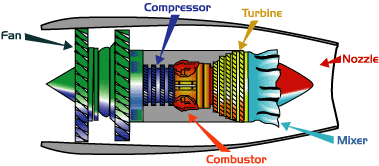
- Fan: This large spinning component used to suck in air in large amounts. The fan blades are made-up of titanium. Moreover, the fan will speed-up this air and divides it into 2 portions. At first, air circles around the chamber as other aircraft components it. The other air called the second part will pass by the inside of the engine. As such, it will pass via a duct whereby it will be useful in generating the majority of the force that will assist in propelling the aircraft forward. Cooler air is useful in adding thrust to the aircraft engine as well as cooling it (Potter 1999). As indicated in the diagram above, the fan is highly exposed since it is through it that we have air intake. When the aircraft is drifting at high speeds it encounters sand-size fragments in the air. These fragments scratch the surface the surface of the fan thus weakening it. The cracks can de sighted by NDT methods and easily corrected.
- Compressor: This is a machine made up of blades moving at high speeds. It compresses air thus producing very high pressures. As a result, this will escalate the potential energy of air. Squashed air finds its way into the combustion chamber (Jennings 2003). When the plane is in an ash cloud, the sand-sized grains of the ash blast against the surface this highly reducing its efficiency. Some effects are only visible after a long time. This calls for frequent inspection on the sharp blade edges.
- Combustor: Just as the name suggests, it is responsible for the mixing of air and fuel and consequently causing the mixture to burn. Spraying of the air-stream with fuel follows on. This will generate a temperature that is high as well as will cause air to flow with a higher energy. “Oxygen from the compressed air burns the fuel thus producing hot and expanded gases” (Edmonds 2003, p.41). Ceramic materials are contained inside the combustor to offer a chamber that is capable of resisting heat as the heat is likely to reach 2700 degrees. When the volcanic ash enters the combustion chamber, it melts thus forming a glassy chemical. This chemical sticks on the surface leading to slow but dangerous corrosion. The solution is by scrapping it off followed by application of another coat/layer of corrosion-resistant alloy.
- Turbine: The airflow from the combustor that is flowing with a higher energy will then go to the turbine. This will cause the blade of the turbine to rotate. The support of a turbine is by the provision of a shaft that serves to linking up the parts and turning compressor blades/vanes. As the gases escape, they hit the blades at an angle thus initiating a rotary motion. Typically, turbines are on the shafts because shafts have manifold ball-bearing sets amid them (Parker 1997). The same glassy surface that occurs in the combustor also forms in the turbine. In this case, it physically blocks air intake thereby halting the running of the engine.
- Nozzle: This is simply refers to the exhaust-duct of an aircraft engine. As Graham (2002) observes, this component is useful in generating thrust for the aircraft. The flow of air that was able to pass the turbine as well as the cool air that was able to bypass the core of the aircraft engine will generate a force while coming out of the nozzle. Conspicuously, the nozzle provides the engine drive and thus the aircraft will move forward. This eliminates mixing of cold and warm air hence no forward thrust. The mixer then exits through the nozzle eventually interacting with air at relatively low temperature. The cool air went around the fan together with hot air from the engine. In fact, the mixer assists in quieting the aircraft engine (Sour 1997). The nozzle fully interacts with the atmosphere; this makes it susceptible to erosion from the volcanic ash flakes.
The Maintenance Procedures
According to Zisfein (2001, p. 43), aircraft maintenance refers to “the preservation, inspection, overhaul, and repair of an aircraft.” The same procedure applies when dealing with effects of volcanic ash. The nature of damage that an aircraft goes through is very wide. This ranges from the frame, engine parts, seals and sealants.
Preservation
This involves taking the right precautionary measures concerning flights that would compromise on the condition of the plane. Apart from the safety measures, frequent check-ups are necessary to ensure that previous cracks are controlled. Sealing the cracks solves the problem and possibly application of another layer of alloy. The skin and airframe are the most critical areas. Volcanic ash has sand grains that abrade the surface. Chemicals also play a key role thus causing cracks if not checked.
Inspection
This stage is very vital. It entails use of NDT methods. This applies to all forward facing surfaces that are edges of wings, light cover, fuselages and windows. Replacement is the first step to any loose bolts, weakened sealants and seals. Volcanic ash has chemicals like feldspar and quartz that react with rubber in the sealants and other plastic connections. If not checked, this may lead to loss of efficiency in the functioning of the aircraft. The other reactant due to volcanic ash is sulphur dioxide gas, which is acidic and causes small cracks on acrylic windows. Therefore, time-to-time inspection is important to keep the plane in good shape.
Overhaul
In this stage, dismantling of the engine takes place together with checking for surface cracks or deposited volcanic ash. The ash melts and sticks in the hot zones. The only way to take care of this is scrapping it off and applying an alloy resistant to corrosion by acids. NDT methods now come in handy to identify and seal fatigue cracks and any pits due to cavitation.
Repair
This last step summarizes all the above since it involves any correction methods to cracks, pits, abrasion and loose joints. It starts all the way from the internal components of the engine to the skin and airframe.
An aircraft is deemed safe the moment it has been maintained properly. A maintenance that is proper and regular will guarantee that the airworthiness that is standard and acceptable through the airplane operational life. The procedures of maintaining an airplane are inspections of aircraft; minimum-equipment lists as well as operating with tools that are not functional, maintenance in anticipation of danger and repair works of movable parts and issuance permits to particular special flights.
It is vital for an aircraft to remain in an air-worthy condition and this can only achieved through maintenance. To achieve this, a number of inspections take place on the engine of the aircraft. These inspections include an inspection on a yearly basis; an inspection after hundred hours; inspecting an altimeter system; check-up before take-off, Trans-ponder inspection; and inspecting other programs. Idyllically, the current maintenance manual provided by the manufacturer is of great use during the inspections, including the unrelenting airworthiness directives, which are with respect to the following facets: replacing parts of an engine of the aircraft, inspections periods and life-limited equipment (Robins 2006).
Nonetheless, it is of necessity to guarantee that the entire instruments of the aircraft as well as the equipment installed are functioning before an aircraft departs. This is possible only through adoption of the minimum-equipment list. Supremely, it of necessity to use the minimum-equipment list because it not only permits for non-functional equipment and items to be deferred, but also escalates the operation of the aircraft. To that effect, it is mandatory to employ the minimum-equipment list (MEL) in an aircraft (Wright 2003).
Ironically, maintenance meant for caution is a not a sophisticated venture. This follows a simple replacement of standard parts on the assembly. In fact, preventive measures must only be the work of recreational pilots, certified pilots and sports pilots.
Repair or changing of any part can be major or alternatively minor. For instance, major repairs as well as major alterations should take place with an entry that is proper, specifically in the records of maintenance. Special flights are also allowed. As Treager (1998, p.77) puts it, a special-flight permit can be defined as “A Special Airworthiness Certificate issued authorizing operation of an aircraft that does not currently meet applicable airworthiness requirements but is safe for a specific flight.” This permission is necessary with aim of allowing the airplane to fly to a basis whereby it is easier to perform maintenance, modifications, or repairs. In addition to that, this permit is significant to allow a functional aircraft that to and to evacuate the aircraft from a danger zone area.
References
Bendict, J., 1992. Airplane Engine. Brookfield, CN: Millbrook Press.
Boyne, W., 1997. Flight. Washington, D.C.: Smithsonian Books.
Chant, C., 1998. Modern Flight Technology. London: Quintet Publishing.
Dalton, S., 1999. Miracle of Flight. Buffalo, N.Y.: Firefly Books.
Edmonds, I., 2003. How Rocket and Jet Engine Work. New York : G.P.: G.P. Putnam’s Sons.
Graham, I., 2002. Aircraft: Built for Spee. New York: Raintree Steck-Vaughn.
Hetzel, J., 1995. Flight: Scientific Investigation. New York: Creative Teaching Press.
Hewitt, S., 2000. Air and Flight. Chicago, IL: Children’s Press.
Hunecke, K., 1997. Jet Engines: Theory, Operation, and Design. New York, NY: Motorbooks International.
Jennings, T., 2003. Helicopters, Planes and Gliders: How Things Operate. Boston: Kingfisher Books.
Little, K., 1997. Airplanes. New York: EDC Publishing.
Lopez, D., 1995. Flight: Aircraft Discoveries. Sydney: Time Life Books.
Maurer, R., 2000. Flight Secret: The Search. New York: Simon and Schuster.
Mellett, P., 1997. Flight: Projects and Concepts. New York, NY: Gareth Stevens Publishing.
Morris, N., 1998. Planes: Traveling Through Time. New Jersey: Silver Burdett Press.
Nahum, A., 1999. Flying Machine: Eyewitness Books. New York: Alfred A. Knopf.
Parker, S., 1997. The Inside of Airplanes. New York: Peter Bedrick Books.
Potter, T., 1999. Aircrafts: Engine Operation. New York: William Collins & Sons.
Richards, J., 1998. Flight: Fantastic Cutaway Book. New York: Aladdin Books.
Robins, J., 2006. The Story of Flight: Did You Know? New York, NY: Warwick Press.
Sour, B., 1997. Aircraft Technology: The Next Generation. New York, NY: TAB Books.
Time Life Books, 2000. Flight: How Things Work. New York: Time Life Books.
Treager, I., 1998. Aircraft Gas Engine Technology. New York, NY: Glencoe.
Wallace, L., 2001. Exploring the Flight Magic. Oklahoma: EAA Aviation Foundation.
Wright, O., 2003. How the Airplane was Invented. New York, NY: Dover Publications.
Zisfein, M., 2001. Aircraft Engine Maintenance. New York: Pantheon Books.