Introduction
After the project components described in chapter (4), all components described will then be integrated in a way to achieve the goal of the project (an Autonomous Robot capable to navigate from one waypoint to other waypoints). There are several experiments though, that should be conducted in a sequence. The experiment, are as follows:
- Extract robot positions coordination data from the GPS module (EM 406) experiment.
- Controlling of DC Motors experiment.
- Robot navigation using magnetic compass (HMC6343) experiment.
- Robot avoided an obstacles experiment.
- The robot navigates from one waypoint to another using (GPS & Compass) experiment and
- Robot navigation with obstacles avoidance using (GPS, Compass and Range sensor) experiment.
In this chapter, all of these experiments will be discussed in detail with results, figures, tables, and comments.
Extract robot positions coordination data from the GPS module (EM 406) experiment
Aim
The first experiment involves the extraction of the robot’s position coordination from the GPS module (EM 406). This is done using an Arduino microcontroller while showing this data on a Laptop screen.
Design
The figure below displays the following:
- 9 V DC Battery wires connected to the Supply Pin of the Arduino microcontroller.
- TX of the GPS module (EM 406) connected to the Pin (4) of the Arduino.
- 5 V of the GPS connected to 5 V of the Arduino.
- GND of the GPS connected to GND of the Arduino.
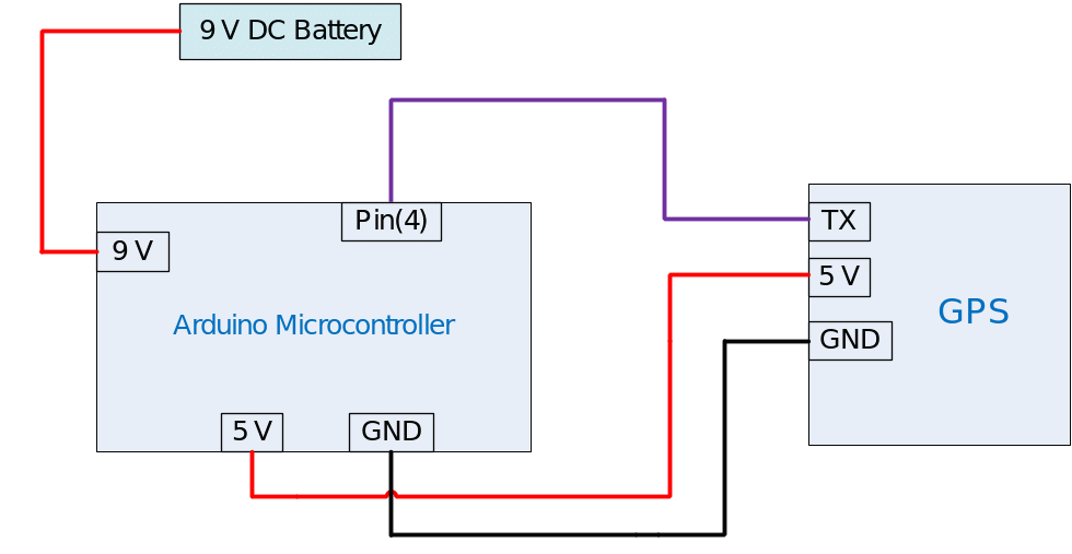
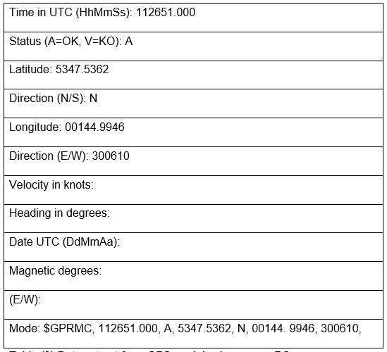
There is no need to connect the RX of the GPS module since there is no need of sending a command from the Arduino to the GPS. The compiling of the code with baud rate of the GPS module is at 4800. This is where information in the format of a GPRMC sentence appears on the laptop screen. It appears as shows in Figure (2).
Results
Comments
- The experiment should be conducted in open area with no adjustments to buildings or trees which may cause a reduction of the GPS reception.
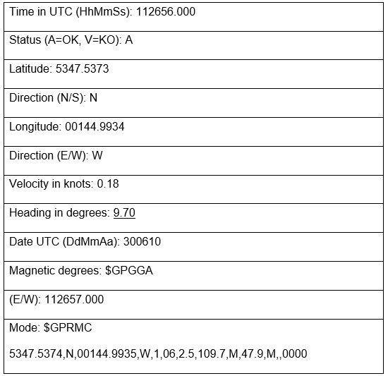
- All the data, especially the latitude and longitude except the heading angle does not show all the time. It is also not accurate for navigation purposes. Figure (3) shows readings from the GPS module (EM 406), which have missing heading angle values making the navigation more difficult. For this reason the compass added to the project gives a very accurate heading (accuracy 2 degrees) angle.
Controlling of DC Motors experiment
Aim
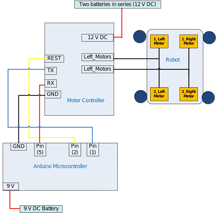
In this experiment, a programming code is written and compiled to the Arduino Microcontroller for controlling four DC Motors (12Vdc, 200RPM Gear head) of the Robot. This is done through the motor controller (Pololu Qik 2s12v10 Dual Serial Motor Controller) to run the four DC motors.
Design
- 9 V DC Battery wires are connected to the Supply Pin of the Arduino microcontroller.
- 12 V DC Battery wires are connected to the Supply pin of the motor controller.
- TX of the motor controller is connected to RX of the Arduino (pin 5)
- RX of the motor controller is connected to the TX of the Arduino (pin 1)
- The rest of the motor controller is connected to the Arduino (pin 2)
- GND of the motor controller is connected to the GND of the Arduino
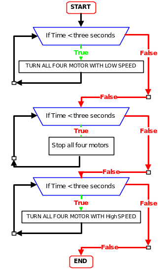
In this experiment several indoor tests are conducted to make sure the motors and motor controller are in working condition. The code here was written to send speed values to the four DC motor controllers in hexadecimals (for example 127 is equal in hexadecimals (0x7F). Figure (4), explains the code logic for the experiment.
A new library file is added to the Arduino library for writing the source code for the motor controller. This library file is called the compacQik2s9v.h library.
Comments
- All four motors work well and the speed can be controlled easily from the Arduino through the motor controller (Pololu Qik 2s12v10). When the code uploads all motors start to move at a low speed for three seconds then stop for three seconds. They finally start to turn all motors for three seconds at high speeds.
- All DC motors have the same performance when they are under the same condition which is good for navigation purposes.
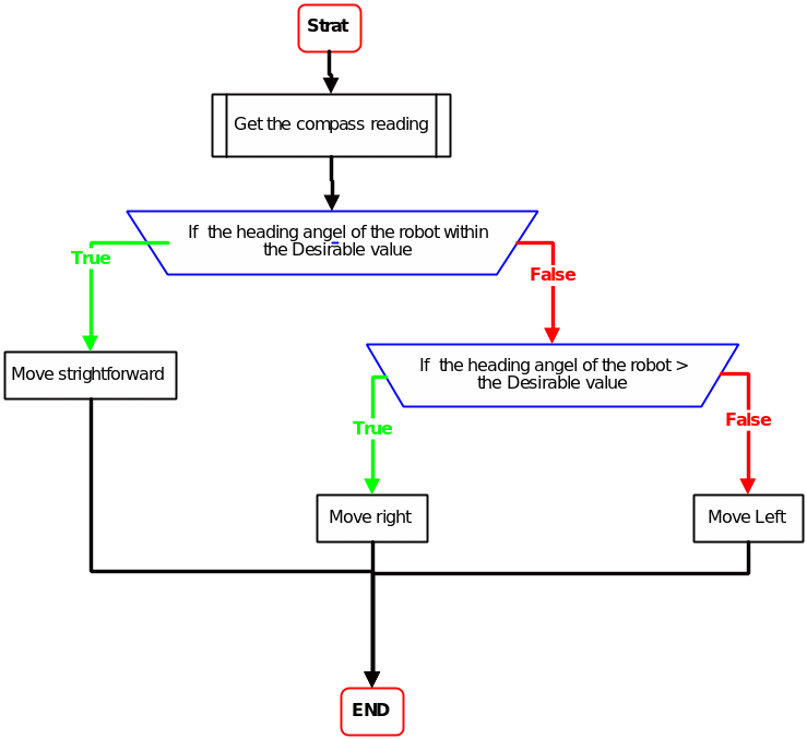
Robot navigation using magnetic compass (HMC6343) experiment
Aim
To experiment to let the robot navigate using a magnetic compass (HMC6343) in a specific heading angle. What is needed is to identify a specific heading angle and read the actual heading value from the compass fitted. After this, a comparison is made between two values with an accuracy of +- two degrees. This is done so that the Arduino sends this data to the motor controller for keeping the robot within the heading angle trajectory.
Design
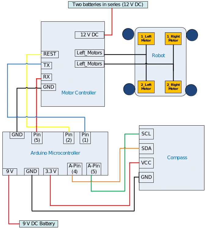
The same wiring as in figure (5) but here the compass PCB is added to the circuit connection as follows:
- 9 V DC Battery wires connected to the Supply Pin of the Arduino microcontroller.
- 12 V DC Battery wires connected to the Supply pin of the motor controller.
- Vcc of the compass connects to 3.3 V of the Arduino
- SDA connects to the analog pin(4) of the Arduino
- SCL connects to analog Pin(5) of the Arduino
- GND of the compass connects to the GND of the Arduino
- Two resistors (10 kΩ) are connected between VCC to SDA and SCL
The flowchart of the programming code for this experiment is shown in Figure (7)
Comments
- The robot starts to search for the heading angle saved in the Arduino and moves accordingly. During movement the robot corrects its direction with the help of a reading from the magnetic compass (HMC6343) and the action from the motor controller (Pololu Qik 2s12v10). But this is only in outdoor trails because in the indoor trials, an error occurred in the compass reading due to metal materials surrounding the robot in the lab or in the room. These materials have an effect on the magnetic compass reading.
- The Robot cannot move on a 100% flat ground because we are using a three axis magnetic compass in the beginning. The problem happened when the two axis magnetic compass was used which caused a wrong reading, as a result of this the robot can now move anywhere (on grass, mountain, etc).
Robot avoided an obstacles experiment
Aim
Designing/building a robot with a program that is able to avoid any obstacle by using sharp sensors in front of it while it is moving
Design
The sharp sensor has three wires; the complete wiring is described as follows:
- 9 V DC Battery wires connect to the Supply Pin of Arduino microcontroller.
- 12 V DC Battery wires connect to the Supply pin of motor controller.
- Vcc of the sensor connects to 5 V of the Arduino.
- Analog Pin of the Rang sensor is connected to Analog Pin (1) of the Arduino.
- GND Pin of the sensor is connected to the GND of the Arduino.
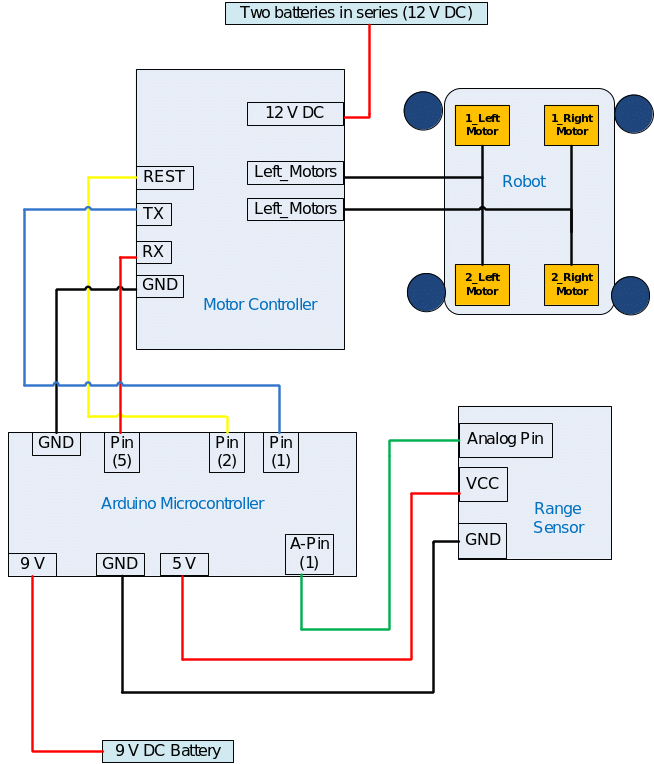
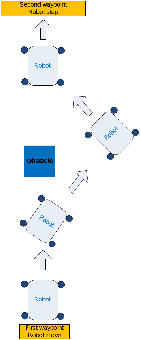
Figure (9) explains how the robot first avoids an obstacle
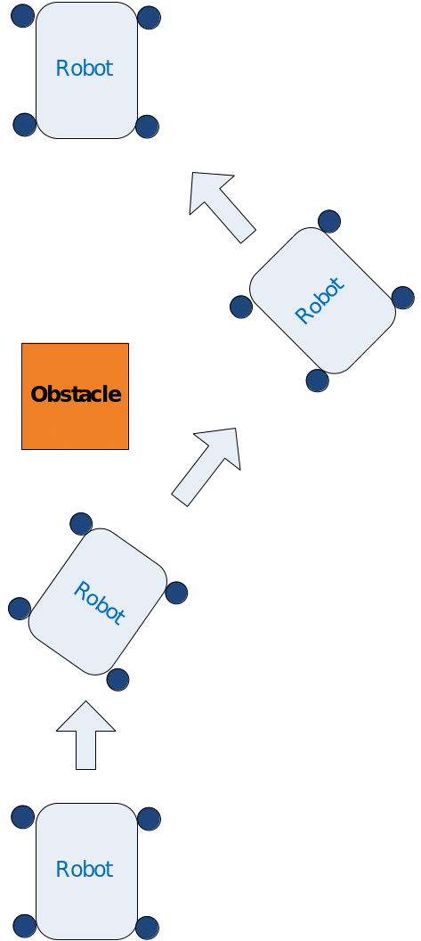
Figure(10) shows a flowchart describing the programming code loaded to the robot circuit for doing the avoidance task, for more information about the code (see Appendix ). An obstacles was put in front of the robot, throughout the experiment the robot successfully avoided the obstacles in away illustrated in figure (9).
Robot navigate from waypoint to another waypoint using (GPS & magnetic Compass) experiment
Aim
To experiment with the robot’s movement from one point to another within a range of a known heading angle going to another known waypoint and stopping there.
Design
The Arduino, GPS (EM 406), motor controller (Pololu Qik 2s12v10), and magnetic compass are connected as follows:
- 9 V DC Battery wires connect to the Supply Pin of the Arduino microcontroller.
- 12 V DC Battery wires connect to the Supply pin of the motor controller.
- TX of the motor controller is connected to RX of the Arduino (pin 5)
- RX of the motor controller is connected to the TX of the Arduino (pin 1)
- The rest of the motor controller is connected to the Arduino (pin 2)
- GND of the motor controller is connected to the GND of the Arduino
- Vcc of the compass is connected to 3.3 V of the Arduino
- SDA is connected to the analog pin(4) of the Arduino
- SCL is connected to the analog Pin(5) of the Arduino
- GND of the compass is connected to the GND of the Arduino
- Two resistors (10 kΩ) are supposed to be connected between VCC to SDA and SCL
Figure (11) explains the wiring of the integrated circuit.
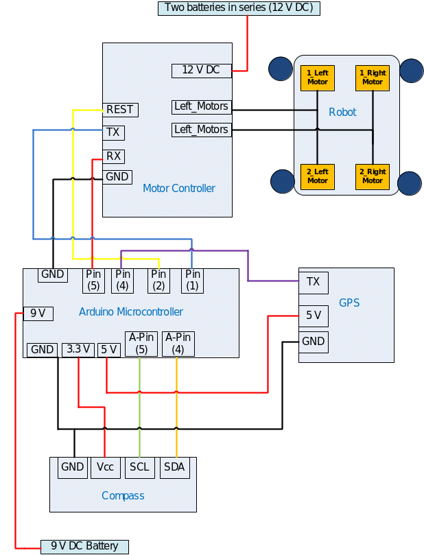
The robot successfully navigated from one waypoint to another one and stopped there with a positions accuracy of 5 meters.
Comments
- The experiment should be conducted in an open area (no building or trees) for ensuring good reception and good results.
- Because the robot has four good quality motors, a proper motor controller, and a battery, the robot moved on flat ground as well as grass with good performance.
- Some speed calibration tests should be done several times to improve the robot’s movement towards the next waypoint.
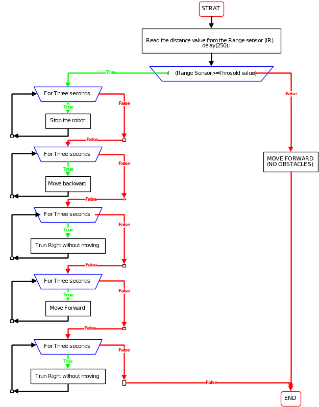
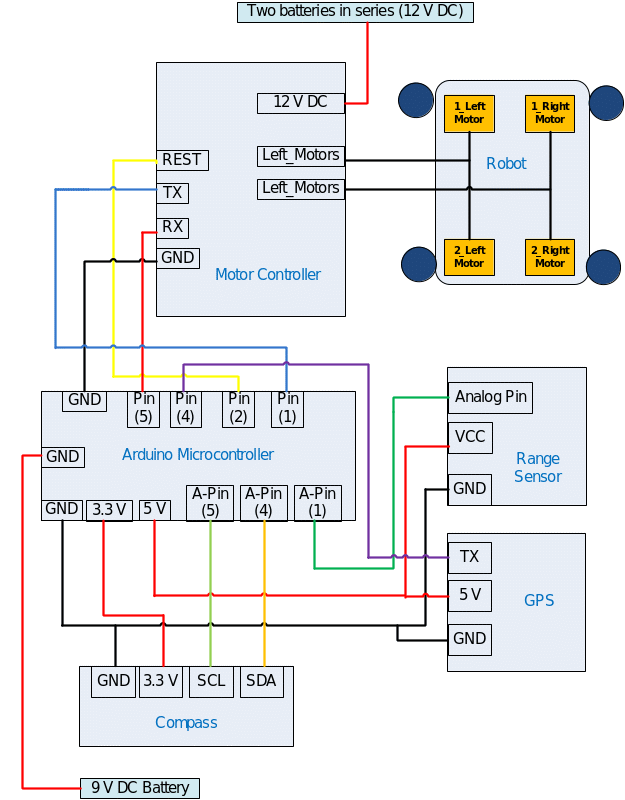
Robot navigation with obstacles avoidance experiment
Aim
This experiment depends on all results from experiments 1, 2, 3, 4, and 5, an integration of all of them in one experiment. In this experiment, the robot moves from a point within a range of known heading angles going to another known waypoint, and stops there. It avoids any obstacles in between by using a range sensor (Sharp sensor), GPS module (EM 406), motor controller (Pololu Qik 2s12v10), and magnetic compass (HMC6343).
Design
The Arduino, range sensor (Sharp sensor), GPS (EM 406), motor controller (Pololu Qik 2s12v10), and magnetic compass are connected as follows:
- 9 V DC battery wires connect to the Supply Pin of the Arduino microcontroller.
- 12 V DC battery wires connect to the Supply pin of the motor controller.
- TX of the motor controller is connected to RX of the Arduino (pin 5)
- RX of the motor controller is connected to the TX of the Arduino (pin 1)
- The rest of the motor controller is connected to the Arduino (pin 2)
- GND of the motor controller is connected to the GND of the Arduino
- Vcc of the compass connects to 3.3 V of the Arduino
- SDA connects to the analog pin(4) of the Arduino
- SCL connects to the analog Pin(5) of the Arduino
- GND of the compass connects to the GND of the Arduino
- Two resistors (10 kΩ) are connected between VCC to SDA and SCL
- Vcc of the sensor connects to 5 V of the Arduino.
- The analog Pin of the range sensor is connected to the Analog Pin (1) of the Arduino.
- The GND pin of the sensor is connected to the GND of the Arduino.
Figure (13) shows all the connections of the experiment.
For this experiment the PCB is designed for the final prototype by using a two layer CAD Software (Diptrace) (the Schematic diagram in Appendix).
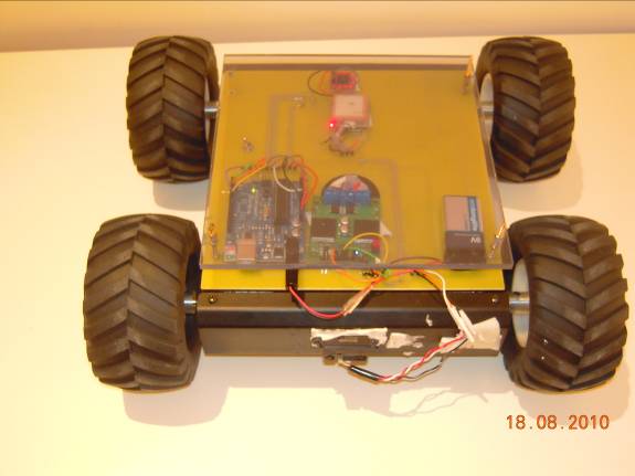
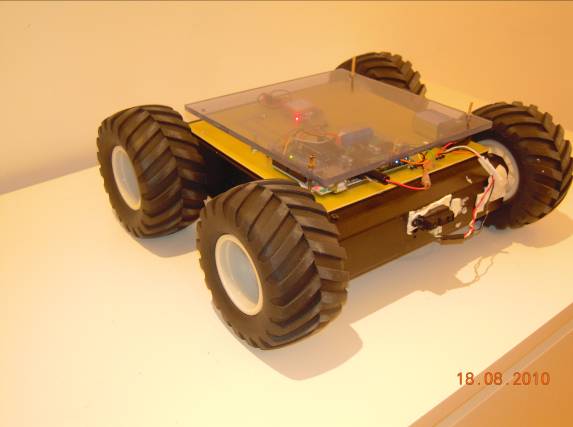
Figure (14) shows the complete Autonomous robot with a first prototype circuit
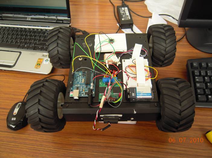
Figure (15) shows a complete Autonomous robot with the final prototype circuit PCB layout
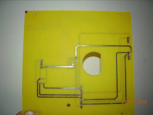
There are four small holes in the four corners for connecting the PCB to the robot platform, one big hole in the middle connects the battery and motor wires to the motor controller and finally one hole for the ON/OFF switch. Figure (16) shows the PCB fitted on the robot and all the components are connected.
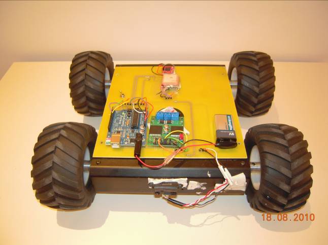
Figure (17) is a flowchart illustrating the programming code loaded to the Arduino microcontroller
- The robot successfully navigates from one waypoint point to another waypoint and avoids any obstacles in between.
- The robot was capable of moving on different surfaces (street, grace, sand)
- The robot was capable of moving in different levels with accurate navigation trajectory, this is because of the use of the three axis magnetic compass.
- The GPS accuracy during the experiments was 5 meters.
Comments
There was a challenge in conducting the experiment outdoors, the challenge mainly included rainy weather conditions most of the days. Generally, it was risky to conduct the experiment and this condition caused delays in the progress of the project. The solution to this, although not 100 % guaranteed, was to put a transparent plastic cover upon the Robot PCB. The bag protected the robot’s components and wiring from rain as well dust.