Introduction
Retaining walls are special types of soil used to support the earth and avoid thoil from moving downwards. The idea is to even out slopes and make available constructive areas at diverse elevations. Therefore, a retaining wall is a construction or a structure designed and built to resist the agile (lateral) pressure emanating from the soil in the occurrence of a necessary change in earth altitude that surpasses the soils or earth’s angle of repose. They offer a lateral hold up to perpendicular earth slopes that would naturally cave in into an extra natural contour. All retaining walls support a kind of “wedge” of soil (Coduto, 2001). A wedge can be simply defined as that soil extending beyond the collapse flat surface of the nature of soil found at the wall location.
A good example of a retaining wall is a basement wall. Cantilevering of the walls starts from the footing going upwards to the grade on the facing to maintain an opposite that is at an elevated. The cantilevered walls have to defy the lateral forces produced by slack soils or, in various instances, water pressures. Therefore, retaining walls are planned to resist water pressures and lateral soil, the outcome of adjunct loads, the wall’s self-weight, and in special circumstances, seismic activity loads in line with the common specified principles (Coduto, 2001).
Qualities of a retaining wall
The ability to recognize and offset the propensity of the preserved substance to shift downwards owing to gravity is the most crucial thought in appropriate blueprint and setting up of retaining walls. The downward movements create immense lateral pressure at the back of the retaining wall. This lateral pressure is analyzed using the “angle of interior friction” commonly, referred to as (phi) with the “cohesive strength (c)” coming from the retained matter, top bearing and the intensity of retaining wall movements (Das, 2006). These earth lateral pressures record zero at the wall tops however, these increases relatively of the highest value with homogeneity of the earth or soil. Earth pressures push the wall frontward or knock over it if not suitably dealt with.
To address the dangers of increased hydrostatic pressure on the retaining wall there should be an efficient drainage system to dissipate any groundwater behind the wall.
The full pressure or force could be understood to perform on one-third starting from the lowest deepness for lateral elongations of homogeneous height. If the retaining wall is not meant to retain water a well designed drainage should be in place to reduce pressure acting on the wall value. It is important to have proper drainage behind the wall to limit the pressure towards the wall’s blueprint value (Coduto, 2001). A drainage system will help eliminate or lessen the hydrostatic pressure and perk up the steadiness of the substance at the back of the wall. Dry-stone retaining walls are usually self-draining. For instance, according to the International Building Code retaining walls ought to be planned in a system that guarantees stability against capsizing, descending, extreme foundation pressure in addition to water uplift. It also requires that the walls be tailored for a safety factor of 1.5 aligned with lateral sliding moreover turning over (Coduto, 2001).
In most cases, retaining walls are designed to provide service for a certain period as determined by the latent durable effects of material corrosion on every substance component involving the wall. Permanent walls ought to be designed to provide service for a minimum of 50 years. A temporary retaining wall on the other hand should have a useful life of at least 5 years. Therefore, the quality of working performance becomes a vital consideration in designing lasting retaining walls. Permanent walls should be designed in a way that retains an artistically gratifying appearance, in addition to having little or no maintenance cost all through the design useful lifespan (Coduto, 2001).
Materials required for retaining walls
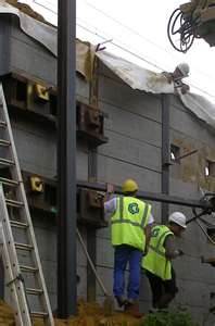
Retaining walls require a myriad of materials depending on the type of a retaining wall. However, there are the common materials that are used for design. They include, wood sheets, interlocking sheets that can be either plastic or steel, armored concrete sheets, pre-cast concrete elements that are either block walls and crib walls, piles that are intimately holed in situ soil cement and soil nailing which anchors the walls into the soil or rock mass.
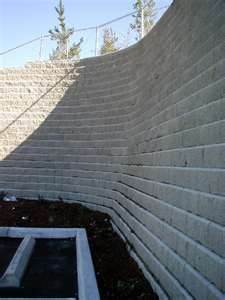
Gravity walls
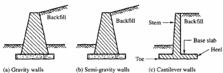
Gravity walls are the first well-known retaining wall structures. They are made from rock-solid material or by mortaring rock rubble jointly. The lateral earth forces’ emanating from the backfill is defied by the heaviness of the retaining wall itself, and owing to their huge nature, they build up very little or no pressure. For that reason, the walls are typically not toughened with steel. Gravity walls are cost-effective for elevations of 3 m or 10 feet (Das, 2006).
Gravity walls are determined by their weight, which is composed of stone, concrete, and other weighty material to defend against pressure coming from the back, which may have a ‘batter’ setback to advance firmness by inclining back to the remaining soil. To obtain pressure for landscaping walls the designer should use segmental masonry, concrete components or a mortarless rock. Dry-stacked gravity retaining walls are elastic and thus do not call for an inflexible traction in frost areas (Das, 2006). House proprietors who put up bigger gravity walls in need of an inflexible concrete foothold can utilize the expertise of professional excavators, which is going to ease the ability to dig a trench for the foundation.
Earlier in history huge weights from stone or concrete were drawn on for very tall retaining walls. Presently, taller retaining walls have been constructed like gravity walls. For instance, geo-synthetic or having pre-cast face; gabions made of mounded steel wire baskets packed with stones or rocks; crib walls that have cells developed log cabin technique as of pre-cast material or timber then packed with soil; or else soil-nailed walls made from soil toughened in position using steel along with concrete bars (Coduto, 2001). The side view figure of the gravity wall is influenced by stability, space utilization at the front of the wall, the requisite wall outlook, as well as the means of construction.
Reinforced retaining walls
Either reinforced retaining walls could be concrete or masonry reinforced walls. On the broaden brass tacks are gravity constructions which present stability against toppling from wall’s heavy weight and reinforcement rods within the wall. The major types of reinforced walls include concrete cantilever wall, buttresses or counter-fort retaining wall, pre-cast concrete wall and pre-stressed walls.
Reinforced soils use Geotextiles or steel to build soil reinforcements that are stacked in sheets in a restricted granular fill. The art of building reinforced soils can be instrumental in making them useful as retaining walls. This can be in the case when a reinforced wall can be constructed as an essential element of the design or as a substitute for reinforced concrete or added resolution based on cost-cutting measure or because of a consequence of the earth conditions. Additionally, if a reinforced wall is built as provisional or corrective or step up works to an on hand design it can be used as a retaining wall. The classification of the walls in this case is based on the use of strengthening bars to ensure a stable soil retaining construction for instance thro soil nailing or reinforcement (Das, 2006).
Cantilever walls
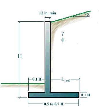
Cantilever walls are constructed using reinforced concrete. They are usually made up of horizontal foothold and a straight up stem wall. The heaviness of the soil mass on top of the heel assists in keeping the wall steady. These walls are efficient for heights going to 10 m or 32 feet. In 2005, the cost of cantilever walls was approximately $ 8
Concrete Cantilever retaining wall
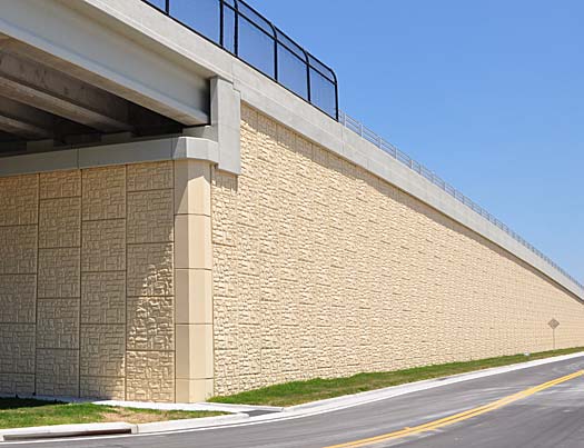
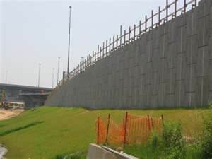
A concrete cantilever wall usually is made up of a wall that is joined to a foundation. A concrete cantilever retaining wall restrains a large quantity of soil; therefore, it should be well designed and constructed. Concrete cantilever walls are commonest applied types of retaining walls. This cantilever wall lay on a slab foundation. Similarly, a slab foundation is back-filled and hence the back-fill mass with add-on smoothens out the cantilever wall and aid it resists any overturning or sliding.
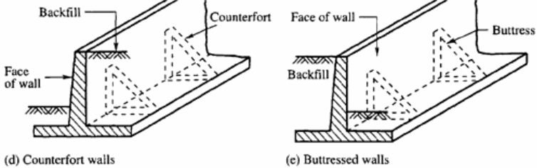
Counter-fort or Buttressed retaining wall
These retaining walls are cantilever walls that apply reinforcing from counter forts colossal at the back and the foundation of the slab. The counter-forts act as both tension stiffeners and attachment to the foundation of the wall slab to get rid of bending and shearing stresses. Counter forts are put into use when there is a need to lessen the bending flashes in straight up walls of enormous height. The counter forts are spaced at expanse apart from one another equivalent or somewhat bigger than one-half of the tallness of the counter forts are applied in the case of high walls having heights going beyond 8 to 12 m (Das, 2006).
Cantilevered walls are constructed from an inner side concrete, which is either cast-in-place, or steel-reinforced or mortared masonry, which usually takes a form of inverted T. These walls beam masses to a huge, structural foothold, translating horizontal pressures at the back of the wall to vertical pressures resting on the soil underneath. Occasionally, these retaining walls are buttressed on the face, or else incorporate a counter fort behind the wall, to enhance their pressure resistance to high loads (Das, 2006). Buttresses can be described as small wing-walls found at right angles to the central drift of the wall. The walls need inflexible concrete footings underneath cyclic ice depth. It requires greatly fewer materials compared to a conventional gravity wall.
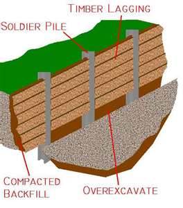
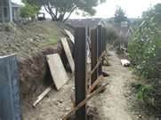
Non-Gravity Cantilevered Walls
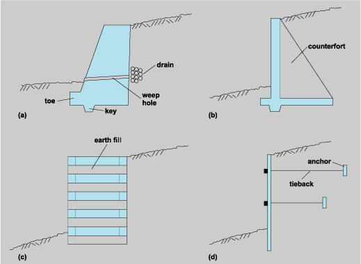
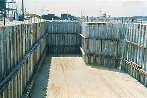
Non-gravity cantilevered wall are built using perpendicular structural components made up of partly entrenched soldier piles or even constant sheet piles. Soldier piles can be built using materials like treated timber, driven steel or pre-cast concrete pipes, or steel piles positioned in bored holes and backfilled using concrete or cast-in-place strengthened concrete. Driven pre-cast or pre-stressed concrete or sheet piles can be used to build permanent sheet piles (Coduto, 2001).
There is wide range of materials that can be used to face soldier piles such as, treated timber, toughened shot-crete, strengthened cast-in-place concrete, and pre-cast material or metal building blocks (Coduto, 2001). A non-gravity cantilevered wall is suitable for both cut and fills an application however is most appropriate if meant for cut applications. Due to the nature of this wall, which has a tapered base width, it is proper for conditions with rigid space constrictions as well as right-of-way constraints.
Mechanically stabilized walls
These are the most cost-effective and commonly built walls. Unlike the other wall types, they are held up by the soil, and not the reverse. Usually, they range between $ 25/SF and $ 45/SF. They are categorized into panel walls, temporary earth walls as well as concrete block walls. Mechanically stabilized earth, commonly referred to as MSE is built using artificial strengthening through encrusted horizontal mats attached at their ends called geosynthetics (extensible) or metallic (inextensible) soil reinforcements within the soil mass or vertical facing elements(Das, 2006).
The mats offer extra internal cut resistance further than that of plain gravity wall constructions. There are other options such as layered steel traps. MSE walls perform like a gravity wall, obtaining their lateral defense using the weight of the resistant soil mass at the back of the facing. Mechanized soil reinforcement typically wants external facing walls such as, Segmental Retaining Walls (SRWs) to attach the strata to or the other way round (Das, 2006).
The wall facing is made of pre-cast concrete elements that can bear various gap movements. Soil mass reinforcement and facing, in that case operates as an enhanced gravity wall. The reinforced soil mass ought to be adequately large to keep hold of the forces from the soil emanating at the back. Typically, gravity walls should have at least 50 to 60 percent the depth or thickness as the wall’s height. There should also be larger than in case of a presence of a surcharge on the wall. Geocells retaining wall is structurally established beneath self- mass and outwardly forced loads, whereas the elasticity of the construction proffers incredibly elevated seismic resistance. The wall’s external fascia cells can be sowed with flora to fashion a green wall.
Usually, MSE walls are utilized wherever conservative reinforced concrete retaining walls are reflected on. They are predominantly compatible for locations where considerable sum and discrepancy settlements are projected. MSE walls are the most economical for filling applications by the nature of their base width being bigger compared to that of usual reinforced concrete retaining walls. The convenient tallness of MSE walls is restricted by the competency of the base material at a specified location. They should not be situated where there are utilities or highway drainage or in a site wherever floodplain erosion or clean might weaken the armored soil mass. MSE walls should not be utilized to hold up bridge abutments through low foundations or mass supported suspension bridge abutments with seismic displacements (Coduto, 2001).
Soldier piles and lagging walls
This was the most commonly utilized among the Roman military engineers and was applied in the case of deep excavations. Compared to other systems, it is comparatively cheap, easy, and quick to build (Das, 2006).
It is mainly narrowed to provisional building, and thus cannot be utilized in the case of high water bench conditions devoid of widespread dewatering and outflow. In addition, it is not as rigid other retaining wall types. Hybrid systems of retaining wall are those that employ both their mass as well as reinforcement to gain stability or resistance.
Sheet pile walls
Sheet piling is usually utilized in supple soils and tense spaces. Sheet pile walls are prepared using steel, pre-cast concrete, vinyl, or timber planks, which are drilled into the soil. Approximately, the matter is typically driven to 1/3 on top of the earth, 2/3 underneath, however this varies as influenced by the setting. Higher sheet pile walls require a tie-back anchor, mostly referred to as “dead-man” sited in the earth at an expanse at the back of the wall facing, joined to the wall, typically through a wire or a bar. Anchors are positioned at the back of the impending failure plane inside the soil (Das, 2006). To come up with steel sheet piles, steel sheets are needed for an excavation or inclination that fits the required depth. This is mostly applied within impermanent profound excavations.
A lot of designers refer to them as most economical in retaining intense earth pressures for soft soils. However, it cannot resist extremely high pressure. They are appropriate for continuous walls designed for water’s edge construction as well as temporary structure wall. Steel sheet pile walls are preferred over other walls for a number of reasons:
- they present greater resistance to driving pressures
- they are lighter, can be recycled for later projects
- have a ling useful life whether under or above water table,
- easy adaptation of the pile length through bolting or welding
- The wall joints are less prone to distort when driving (Das, 2006).
Alternative Retaining Techniques
Soil nailing
A soil-nailed wall entails soil reinforcing as the work continues at the site of excavation by introducing bars, which operate in tension, referred to as Passive Bars. The bars are analogous and a little trending downward. They can as well operate partly in bending or shear. The skin friction between the soil and nails acts to generate tension within the nails.
Steel reinforced bars are drilled into slopes, retaining walls or through excavations using slender units. By the use of already drilled pre-opening, the bars are grouted into the excavation, or carry out both drilling and grouting at the same time. They are typically bedded in without being tensioned at a slender descending inclination (Das, 2006). An inflexible or flexible face that is always drenched concrete or secluded soil nail heads can be drawn on at the face.
Soil strengthening
Some various techniques or systems do not just comprise the wall itself, however condense the earth, or ground pressure against the wall. These techniques are commonly applied in a blend with a particular or any wall type; however, some builders might just employ it as facing especially for visual purposes.
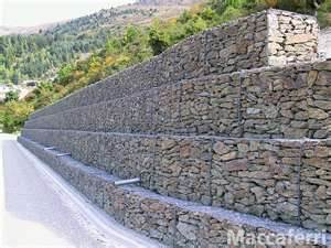
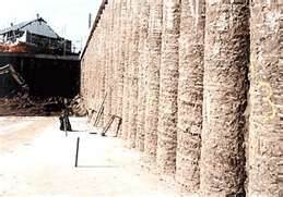
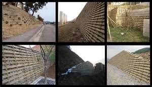
Gabion walls
These are walls used for soil strengthening and mostly without an outer wall made from gabions that are multi-celled, soldered wire or just wire net boxes that are rectangular that are subsequently rock filled. Depending on the use, they can also be filled using sand or earth. They can be described as gabion elements fixed to geo-grid ‘tails’ pulling out into reinforced soil (Coduto, 2001). They are used to build structures that control soil erosion as well as stabilize the steep slopes. Gabions have a wide range of application that include; acting as retaining walls, wing walls, provisional check dams, bridge abutments, channel aprons, culvert headwalls, parking security walls as well as beach and shore security walls. To control erosion gabions with caged riprap are often used, while metal structures are applied in the case of dam or foundation construction.
Slurry walls
Slurry walls involve a construction technique of excavating a deep channel having a unique bucket with a crane. As the trench gets deeper and deeper, the earth is barred from caving into the trough by maintaining the opening full with “slurry”. The slurry is a combination of water and bentonite, which belongs to the Montmorillonite clay family. This bentonite thickens the slurry, but maintains liquid (Coduto, 2001). This is important to keep lateral walls of the soil from crumbling into the trench or excavation. When the hole attains the proposed intensity, the excavation filled with slurry is armored with steel and cautiously filled up with concrete.
Most slurry walls are constructed to 100-foot lowest point, and vary from 2 to 4 feet in breadth. Usually, the panels range from 15 feet to 25 feet lengthy, and are connected by tongue along with groove kind seals (Coduto, 2001). This helps avoid the incursion of groundwater insides the prospect underground site. The greatest benefit of slurry walls is that they are stiffer compared to sheet piling. They also have a greater and better ability to support the soil than lagging and steel sheets or soldier piles. Additionally, they are inclined to be waterproof than other excavation techniques.
Secant pile walls
A secant pile wall is made by an intersection of singular reinforced concrete piling. The piles are constructed from bentonite or drilling mud combined with augering. These piles should also overlap by approximately 3 inches. An alternative to these secant piles are tangent piles and in this case, the piles do not overlap at any time. Tangent pile walls are built swill out with one another. The outstanding benefit of secant pile and tangent wall piles is the augmented alignment elasticity. The pile walls in addition could have better rigidity, and the building process is not as noisy. However, the joints are limited in terms of being watertight; the piles are also quite costly and it is difficult to attain vertical tolerances used for the deeper piles (Coduto, 2001).
In-situ walls
In-situ walls do not depend on their mass or weight to hold up the soil. Instead, they count on their flexural forces for soil retention (Das, 2006). The walls are held with infiltration into the earth or else using anchoring structures for instance in the case of soil nailing.
Crib walls
These retaining walls comprise intertwining individual boxes made up of treated timber or pre-cast concrete. The individual boxes are after that stacked with crushed stones or any other crude grainy substance to produce a freed raining construction. The crib walls are into two groups, that is timber or reinforced pre-cast concrete.
Anchored Earth walls
These retaining walls use face units that are attached to bars, rods, or strips with their ends fastened into the soil. These anchors are similar to abutments. The tying cables should be highly potent and with typically pre-stressed tendons. Strip ends are specially designed to grip the soil and the strip well (Das, 2006).
All the above mentioned methods can be used to structure an anchored wall however it is important to enhance strengthening through cables, extra stays anchored behind soil inside the rock. After driving the anchors into the material through boring, they are then stretched out at the cable terminal, either through mechanical way or habitually by introducing pressurized concrete, which in turn inflates to structure a bulb within the soil (Das, 2006). Theoretically intricate, this technique is extremely practical wherever towering loads are anticipated, or if the wall itself is, lean and would on the contrary be too weak.
Conclusion
From the above discussion it can be concluded that the topic of retaining walls is of significance since for a long time, theory proponents have employed numerous techniques to evaluate retaining walls as well as their impact on the adjoining soil mass, or to examine the soil mass and its influence on the retaining wall. Now, nearly all retaining wall designs are founded on any of the three methods of analysis. These are:
- Earth pressure theory developed by Coulomb and Rankine
- Apparent earth pressure advanced by Terzaghi and Peck
- Limit equilibrium developed from analysis work on the stability of earth slopes
Presently, many designers work effortlessly amid these three theories, shifting from one analysis to another in mid-examination nearly lacking acknowledgement. Consequently, an organization of literature subsists to devise walls, which are mainly founded on practice and banks on successful prior design histories. Apart from the need to acquaint the user or reader with differences noted in the different methods, no effort will be put forward in this case to meticulously elucidate their workings. The bibliography provided in this thesis tenders reading which will supply the reader with additional information as regards to these design techniques.
Many designers though, have faced intricacies as regards to walls they have designed since they have only concentrated on the wall like a lateral weight-resisting component (Das, 2006). For the planner to center merely on the side loading specified in the diverse design methods before investigating the total loading system which could subsist in a wall might result in troubles if not utter failures. Nevertheless, it is very important to understand all the pressures operating on a wall to effectively design a shored wall. Usually, the designer is largely apprehensive with horizontal pressures working to tumble the wall down the excavation (Das, 2006). On occasion though, vertical weights on shoring ought to be considered as a necessity.
When the safety factor is below 1.5, it is important to lengthen the shoring wall beneath the excavation to facilitate safe completion of the excavation to lengthen the failure path (Das, 2006). Various designers hold on to the belief that using bendable retaining system can be used to increase the factor of safety for instance, sheets piling and therefore, a further rigid wall for example, a secant or a slurry wall may be required to enhance the capacity of the excavation.
When dewatering of a shore-lined excavation in soils with less cohesion is performed, moreover the shoring is not pulled out to a soil layer, which will discontinue the water flow from outer surface of the excavation. The designer has to make certain that basal volatility will not take place due to the flow of water beneath the wall and uphill in the direction of the bottom of the excavation. This possibility can be examined by building up a gush net to study the base stability of the excavation.
References
Coduto, D. (2001). Foundation design: principles and practices. University of Michigan: Prentice Hall
Das, B. M. (2006). Principles of Foundation Engineering. New York: Thompson Learning.