Introduction
Water shortage is a major global problem more so in arid and semi-arid areas. Both population and weather changes contribute to the increased water shortages affecting various nations globally. The nations, however, possess a wealth of seawater resources that could effectively be used to generate water for use by the residents. Although this potential is widely recognized, the use of solar thermal energy for seawater desalination is not yet widely exploited commercially. This is given the fact the existing technology still bears increased levels of feasibility as compared to the use of solar thermal energy. Such technologies include conventional thermal distillation and reverse osmosis technologies. However, it is acceptable that room for improvement of technology application to desalination based on thermal solar energy is available (Encyclopedia Britannica, 1999: 56)
Solar ponds are among the best possible proposed options for efficient low capacity production plants. This is taking into consideration low water requirements and the pricing of land. Higher desalting capacities however necessitate the use of other technologies alongside thermal solar technology including conventional distillation. (Hills, 2003: 56). Multi-Effect distillation plants are subject to high setting costs and ostensibly high efficiency (Hussain 2003: 76)While in the sixties, no large scale MED plants were constructed, the last decade has however seen increased interest in MED and consequently a renewed interest in this processes usage via solar ponds in desalination of seawater. Currently, this method is competing for both technically and economically with other desalination methods (Kaul, 1987).
Recent research developments on processes involving low temperatures have led to an increase in the capacity to desalinate seawater and additionally, reduced the consumption of energy during the process (Talbert, et al. 1970: 89). This provides that the system operates on a long-term basis and operates on a long-term basis. In the development of solar ponds for seawater desalination, among the important factors to consider include:
- High system reliability both for the solar collector and the MED plant.
- Low thermal inertia with regard to the coupling of the solar collector field with the MED plant.
- Specific electricity consumption should be at reasonable levels.
- The plant’s performance ratio should be in the high range.
Efficiency and cost considerations are fundamental to establishing the feasibility of such a project. Basically, a solar thermal energy desalination plant is as shown by the schematic diagram shown below:
Project aims/objectives
Implementation of projects is often a very complex problem and little oversights could cost the implementers lots of cash. This paper evaluates the feasibility of a Solar Pond for Seawater Desalination. To achieve this it aims to attain the following:
- Elaborate on the economics and costs of using solar ponds for Seawater desalination.
- Establish the efficiency of solar ponds in seawater desalination.
- Compare the costs to that of other existing technologies.
- Elaborate the costs against the existing needs and expected gains of the affected areas.
Methodology
Research methodology
It is important to mention that this paper will not engage in primary research to establish the costs and processes associated with other techniques used in seawater desalination. Instead, this will be borrowed from existing literature in the same area. The first approach to study methodology will therefore involve a review of existing literature materials. This will provide the basis for comparison with regard to the cost and process consideration as will be established for the case of thermal seawater desalination.
This paper’s primary focuses will, however, be on costs and process considerations associated with solar pond seawater desalination. This will take two major approaches which will include pond construction consideration, solar field analysis, and desalination unit analysis.
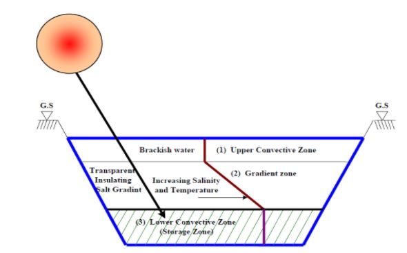
Salinity Gradient Solar Pond
A salinity-gradient solar pond (SGSP) acts as a body for the collection and storage of solar energy. Often it is classified into three distinct regions namely: upper convective or surface zone, main gradient zone (MGZ), and lower convective or storage zone. The UCZ is homogenous and contains low salt solution concentration and likewise, LCZ is homogenous but has a high salt concentration which is either convecting or stratified based on temperature. The middle layer is non-convective which is the MGZ and is constituted of a thermally insulating layer in which salinity changes with depth. Insolation is absorbed and stored by the pond in the lower region. The temperature in this region typically ranges from 60 – 90°C.
The important parameters in studying the ponds feasibility in seawater desalination:
- Distillate production rate
- Solar pond heat input
- The consumption rate of energy (thermal and electrical)
- Performance ratio (energy required to evaporate distillate/energy used)
- Recovery ratio (volume of distillate produced / volume of feed)
The distillation production rate is calculated using the equation shown below:
![]()
The solar pond heat input is calculated as shown below:
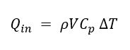
Where: ρ = is the density of the saturated brine of the solar pond
V = volumetric flow rate of the hot brine through the heat exchanger
Cp = specific heat of the brine
ΔT= the temperature difference of the hot brine between the inlet and outlet of the heat exchanger.
The solar pond heat input,Q is applied in thermal energy input calculation and performance ratio calculation
Qin represents the total input of heat including heat used in distillation and heat losses as the process takes place.
The calculated performance ratio must be conservative. Recovery ratio calculation is based on the balance of mass of salt and water.
The equation is given as shown:
![]()
Where, Vfeed, Vdist, and Vcon represent feed water volumes, production distillate, and brine concentration respectively and Cfeed, Cdist, and Ccon represent total solids dissolved, distillate, and the concentrate respectively. For a steady-state of production, the equation below represents it.
![]()
And hence the recovery ratio is given by
![]()
Desalination unit
The heated seawater from the “solar pond” goes to the desalination unit for the production of freshwater. The desalination unit is the regular multi-effect distillation unit (MED) type. Normally, these MED units are used for brine temperatures of approximately 1000C (2120F) and thus would seem inappropriate at a first glance, for this scheme a maximum brine temperature of 600C (1400F) will be presumed.
As can be expected the output from the solar pond unit depends upon the brine temperature entering it. For different months the output of the unit is calculated. The distillate output starts as soon as the outlet temperature from the “solar field” reaches 32.20C (900F). Thus its operations differ from month to month. For instance, it will be assumed that in the month of June the scheme operates for 24 hr while for the month of March it works for 19 hr and for the month of January only 9 hr (Brice, 2007).
Pumping requirements
The seawater has to be pumped from the Sea to the desalination site, which involves a distance and probably an elevation from sea level. The pumps, hence, should be large enough to overcome the pressure loss in the feed pipes and the elevation. The cost of feed pumps will therefore be considered. Pumps in the MED unit should be able to overcome the pressure loss in heat exchangers as well as be able to create enough suction for flash evaporation. For the pumping in the MED plant, we have extrapolated on the design given by Brice et al. (2007) to suit our requirements will form the basis of the study.
Thermodynamic aspects of a desalination process
The energy required for a desalination plant to convert seawater to drinkable water is high. In this paper, the assumption is that the intake stream for the desalination process is ideal (Brice, 2007). This implies that there is no change in volume when the two components (water and salt) are added independently, no heat of mixing is generated, but there is still a change in the entropy of the system – All the work that is added to the system comes in the form of heat, or by the second law of thermodynamics, the entropy of the universe is increasing in the form of heat flow (Brice, 2007).
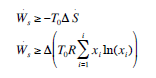
Therefore, for an ideal mixture, the minimum work required to perform the separation is described by the following expression:
![]()
Two cases are involved in the desalination process.
- Separation of the intake stream to pure water and pure sodium chloride.
- Separation of the intake stream to pure water and concentrated brine, assuming that the concentration of the brine is twice as the intake stream.
The key variables that are fundamental to the evaluation of heat energy transfer involved in solar ponds energy use in desalination of seawater include:
![]()
![]()
![]()
![]()
![]()
![]()
![]()
![]()
![]()
![]()
![]()
![]()
![]()
![]()
![]()
![]()
![]()
![]()
![]()
![]()
![]()
![]()
Disposal of effluents
This will involve the evaluation of costs associated with their disposal. It is worthwhile to look at the effect of effluents on the marine environment. Very little work has been done on this aspect, but the studies do indicate (Miller, James E. 2003) that there is very little or negligible effect on the marine environment. Specifically, in our case, the harmful effects will be negligible to the environment.
Cost Analysis
In any project of magnitude and complexity, the calculations for the cost of water can at best be an approximation. There is a multitude of local conditions that have to be taken into account for the final figures. In the absence of any such data, like the cost of water in this region, cost of other alternatives, and the payback mode for a desalination plant, it is appropriate that a simple-minded cost calculation based on the capital and running cost of the system should be sufficient. The capital cost includes the cost of wind machines, the cost of 20 stages MED unit, and the cost of concrete tubes. Also included in the capital cost is the labor, which has been taken arbitrarily to be 20 percent of the capital cost. The running cost includes the maintenance and the chemicals for scale reduction. Based on the existing technology for such plants (Perry, & Green, 1997). the maintenance cost has been taken to be 7 percent of the capital cost. The cost of the wind machines is based upon the projected cost by DOE for the 1980s (Spiegler, 1977) which is $2500 kW. For concrete collector tubes the existing market price of $12.50/ton has 10 been taken. We do believe that large-scale production of concrete locally will be much cheaper than this price. The MED desalination technology is quite developed and thus the cost of such plants has been extensively surveyed (Perry, & Green, 1997). Based on such cost figures, the desalination unit cost has been calculated. Brice et al. (2007) give detailed costs for a MED desalination unit operating at 600C (1400F) brine temperature. We have interpolated this design for condensing area requirements and cost for the present scheme. Assuming that the present plant will provide water for 290 days in a year, the cost of water per 3.79 m3 (1000 gal.) is:

Where η = number of years.
Naturally, this cost should be compared with the cost of water obtained from an alternative supply of water.
Research plan
The research is scheduled to run for a six week period as illustrated by the Gantt chart below:
Literature Review
Solar ponds
A non-convective solar pond is a potentially large surface area solar collector device. It has the additional advantage of long-term storage capacity. It is a shallow body of water of about a meter deep containing dissolved salts to generate a stable density gradient (fresh water on top and denser salt at the bottom) (Tabor, 1981: 184). Part of the incident solar radiation entering the pond is absorbed leading to temperatures near 100°C without convection due to the density gradient (Niesen, et al. 1977). The hot saline water is used in several applications including driving turbines, generation of electricity, and providing hot water for use in industrial and commercial purposes as well as space heating among others. (Rabl & Nielsen, 1975: 218).
Sun shines over ponds and lakes allow absorption of some irradiation and warming up of water. The absorbed heat is quickly lost as a result of convection with ambient air (Virk, et al. 2001: 150). Convective circulation then takes place with warm water rising and the cold water on top moving to the bottom. Salinity gradient solar ponds are constructed in a manner that the circulation as a result of convection is barred from occurring by ensuring that the bottom of the pond is kept denser than the top part. This allows storage of the energy absorbed at the bottom of the pond. This is done by the creation of three layers within the pond each having different temperatures and saline content. The regions include Upper Convective Zone, Gradient zone, and the Lower Convective Zone (Storage Zone) (Virk, et al. 2001: 152). The top layer usually ranges from 0.8 to 1.0 meters in depth and bears a temperature similar to the atmospheric temperature and reduced salt concentration. The second layer is known as the gradient zone and temperature as well as saline concentration increases as the depth increases. It usually ranges from 1-2 meters (Batty, C. J. 1986). The bottom solar pond layer is also known as the storage zone and is most dense and often heated to up to 100°C (Virk, et al. 2001: 153). The stored heat is extracted when brine is passed via an external heat exchanger. The ponds require plenty of lands, water, and salt making them more feasible in wasteland and desert areas. Various researchers argue that using this technology would enormously limit the production costs associated with the process of desalination. The diagram below illustrates a solar pond.
Salinity gradient solar ponds act as heat collectors from the sun and additionally offer storage for the same. Brine from solar ponds is usable for various industrial purposes including as a heat source for vaporizing feed-water in MSF or MED desalination, for space/water heating, to dry grain, and in electricity generation, among other uses. Solar ponds are able to store heat due to their unique chemically stratified nature (Tabor, 1981: 186). There are three layers in a solar pond: the upper or surface layer, called the upper convection zone (UCZ), the middle layer, which is the non-convection zone (NCZ) or salinity gradient zone, and the lower layer, called the storage zone or lower convection zone (LCZ). Salinity increases with depth from near pure water at the surface to the bottom where salts are at or near saturation. Salinity is relatively constant in the UCZ and LCZ and increases with depth in the NCZ. Saline water is denser than freshwater; therefore, the water at the bottom of the pond is denser (has a higher specific gravity) than water at the surface (Tabor, 1981: 187).
Muniz & Skehan, (1992: 30) assert that solar pond systems are able to store heat because density differences associated with salinity suppress circulation within the water stratification layer. The salinity gradient of the NCZ represses hot water convection to the surface. It follows then that despite the ability of solar energy to penetrate the depth of the entire pond, it lacks the ability to escape the zone of storage. UCZ temperature is equal to or near the ambiance temperature (Tabor, 1963: 191). LCZ temperatures can reach or even exceed 90°C. The zone receives heat proportional to incoming radiation from the sun and has inverse proportionality to thickness. Storage zone temperature is dependent on a number of factors. These include intensity and solar insolation period, NCZ thickness, ambient temperature, and salinity gradient.
The surface area of ponds often ranges from 100 to 1,000,000m2 and have depths ranging between two to four meters. Approximately one-third of the pond is comprised of the LCZ. Usually, a device for suppressing the waves is floated over the surface of the pond. In some instances, a complete cover is used to minimize heat loss and contamination of the pond’s water. The fact that salinity gradient needs t to be physically constructed using solid salts and a relative amount of freshwater, access to and the cost of salt and water for initial construction of the pond is a vital factor. Another constituent of the pond, that is vital and yet very expensive is the pond’s liner. In many instances, the pond’s bottom and sides need lining to bar groundwater from contaminating the pond. Liner costs and salt costs are the most significant factors affecting the overall cost of construction of a solar pond.
Solar insolation intensity and period affect active zone temperature and consequently the temperature of operation of distillation units coupled to the solar pond. Other vital factors which affect site selection for SGSP are the speed of the wind, debris resulting from wind, and evaporation to rainfall ratio as well as the slope. Elevated wind speeds can produce turbulence in the UCZ. However, it is important to note that this does not pose a significant problem given that the UCZ merely insulates the NCZ region. UCZ additionally, protects the gradient of salinity from erosion caused by environmental factors. UCZ thickness is often increased when cases of high-speed wind are predicted during the feasibility study thus ensuring that the UCZ remains unaffected. Baffle systems are often used to protect the ponds from winds which at times involve covering the entire surface using transparent plastics.
Various solar pond-powered desalination facilities have been proposed and/or tested. Solar ponds researchers are in consensus that this technology is effective for thermal distillation applications. Its preference is based on the fact that ME, MSF, and TVC successfully undertake effective operation at temperature availed by the solar ponds (50 to 90 ºC).
Advantages of solar ponds
A lot of solar collector devices are now known. However, none has succeeded in overcoming the periodicity problem of solar energy as a solar pond. A solar pond is capable of storing energy for use in the black month (1-4 months depending on the Latitude) during the peak season in higher latitudes (7). This is particularly useful in the northern part of Nigeria with extreme temperatures during the harmattan season. Energy stored in the afternoon can be used at night and the following morning.
Apart from the storage capacity, it has helped to overcome the limitation of other collectors to harness sufficient solar energy that can be used for power production (8), process heat (9), space heating (10), and desalination (11).
Here at home, it could be used to generate electricity to a remote area that is yet to be connected to the national grid, process heating for industrial purposes, and space heating for both domestic and industrial heating. The yearly occurrence of the house burning in an effort to reduce the effect of cold harmattan haze can be reduced in the future. Also, the heat stored during the day can be used to power the generator side of an absorption refrigerator for comfort cooling.
The inexhaustible nature of solar energy, coupled with availability, cheapness, cleanliness, non-destructive nature to the environment and renew fuel crisis of 1973 till date and subsequent concern about the availability of conventional fuel (fossil fuel) brought about a renewed appraisal of solar ponds out of all other systems because of its storage capacity and large collector area.
Solar Pond Technology
Lining Materials
The pond is linked at the bottom and sides with suitable material that must be impervious to the salt solution in the pond and groundwater around the pond and secondly, be ‘impervious’ to the heat developed in the pond due to solar radiation. The ability to resist ultraviolet degradation and minimum mechanical strength is an added advantage. Compacted soil, plastic, elastomer, and reveal (13), a patent laminated fabric (terylene cloth) impregnated with fiber-glass and coated on either side with bitumen are used today.
Filling Of the Pond
Two different methods can be used to develop the salt gradient. One approach is to start with the densest later (saturated brine solution) below and consequently float the denser layer on top-up to the lighter layer (freshwater). Another approach is to start with the fresh water and then introduce denser layers at the bottom which will lift the lighter layers previously filled (Tabor & Matz, 1965: 48).
A typical application of the first approach consists of partially filling the pond with high salinity brine and pumping fresh water through a diffuser that is immersed in the upper portion of the existing solution. The diffuser is progressively raised to the surface either in continuous motion or in discreet steps of about 5.0 cm (17). The pond obtained can be categorized into 3 zones. The upper convective zone (UCZ) of the low and uniform salt gradient at a constant temperature that is very close to the ambient temperature. Convection is due to thermal cycling, wind action, and the effect of both the temperature and salt gradient at its lower boundary. Immediately below the UCZ is the non-convective zone (NCZ) with salt density increasing with depth. It serves as an insulator and heat storage zone. It is known to effectively transmit incident solar energy to the storage brine below as its thickness is reduced and at the same time serves better as insulation for the storage brine as thickness increases. However, there is a maximum level of thickness that allows maximization of energy collection rate (Tabor & Matz, 1965: 49). At the bottom of the NCZ is the lower convective zone (LCZ) with constant salt and temperature gradient. This is the heat collector, heat storage, and heat removal medium. The bottom boundary is a black body.
Due to diffusion (though very small indeed) of salt upwards from the higher to lower concentration, the salt gradient will be effected gradually. The rate of movement of salt flux upwards qs is given by:
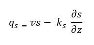
where ks is the coefficient of salt diffusivity, v is the velocity, s is salt concentration and z is depth. Thus, if water is removed from the bottom of the pond to give v a value
![]()
then qs=0 and salt remain stationary in space. This is known as the ‘falling pond’ concept (Tabor & Matz, 1965: 46). A flow system to carefully add salt to the bottom at the top had been developed (Tabor & Matz, 1965: 51).
Some recent pods used salt (e.g. borax or potassium nitrate) which exhibits a high increase in solubility with an increase in temperature. The pond is filled with a saturated solution left over at the bottom. When the pond is heated up, more salt goes into the solution and convection does not occur (Tabor & Matz, 1965: 52). Inexpensive transparent plastic materials are often used to suppress heat loss via convection to the environment.
Thermal Energy in Non-Convective Solar Pond
Solar radiation incident upon a horizontal surface of the earth is a function of latitude, the day of the year, the time of the day, and the atmospheric conditions. The energy is received as both direct and diffuse radiation and is distributed over the spectrum in the ultraviolet, visible, and infrared (Hull, 1982: 387).
Fraction of the radiation reaching the surface of the pond will be reflected and the remainder that penetrates the pond result in thermal energy. This fraction in a day can be calculated from the following equations which are obtained from Fresnel’s equation (Hull, 1982: 387):
![]()
![]()
![]()
where E is the ratio of radiation penetrating the water surface and incident upon a horizontal plane just below the surface to the radiation incident upon a horizontal plane above the water surface and incident upon a horizontal plane just below the surface to the radiation incident upon a horizontal plane above the water surface; i = the angle made by the incident radiation with the normal (solar zenith distance); n = indexes of refraction of the salt-water solution at the surface (≈1.33 for very dilute solution); and r = the angle made by the refracted ray with the normal.
From Snell’s law: ![]()
Fraction of diffuse radiation ![]()
The solar zenith distance can be measured or calculated by
![]()
t = time in hours (noon =12)
Ø = declination of the sun ≈
![]()
δ0 = declination of the sun at equinox
= 23 degree, 27 minutes
D = number of days
From Bonguer’s law, the transmitted radiation
![]()
Where q is the intensity of the incident radiation of wavelength λ
αλ is the spectral absorption coefficient
z is the thickness of the homogeneous absorber.
Therefore, the spectral transmittance (23) is
![]()
and the spectral absorption coefficient is expressed by
![]()
The heat transfer processes in the solar pond are governed by a one-dimensional time-dependent heat conduction equation (Hull, 1982: 388).
in which ρ is the fluid density; c is the specific heat of fluid; T is temperature; t is time; z is vertical coordinate; K is coefficient of heat diffusion; q is the source of thermal energy and qs is removal rate of thermal energy. A complete treatment is of course complex because of the large number of variables involved.
According to Hull (24), the thermal efficiency of the solar pond is
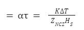
where ΔT is the temperature difference across the NCZ and HS is the surface insolation.
Evaporation pond cost calculations
A report by the US Bureau of Reclamation presents Mickley’s equations for calculating the cost of utilizing evaporation ponds for desalination concentrate disposal (Boegli, Dahl, & Remmers, 1983). The equations take into various costs including land purchasing costs, land clearing costs, pond excavation costs, costs associated with the building of dikes, pond lining costs, fence installation, and access road construction (Muniz & Skehan, 1992: 78). The entire area needed for the evaporation pond takes into consideration the area of evaporation, dike area, and the pond perimeter. Mickley’s equation for obtaining the total area and the associated total unit area capital cost is as shown below:
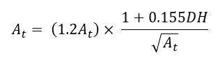
Where
And
![]()
Where
Conclusion
Thermal desalination using salinity-gradient solar ponds is a promising desalination technique using solar energy. These ponds bring in solar energy collection techniques alongside storage to provide reliable thermal energy at estimated temperatures of between 50 and 90°C. The technical and feasibility of this process are fundamental to decision-making regarding the same. Feasibility focuses on the dam’s long-term reliability, provision for improvement f its thermodynamic efficiency, and its economic aspects.
Evaluating the feasibility of using solar ponds in seawater desalination requires a deep and critical evaluation of the individual; components that constitute the desalination system. This begins with an evaluation of the cost implications of such a project. Questions regarding the cost of construction in relation to output and ultimately the performance of its intended function are vital in order to establish how feasible it is. Like most feasibility study initiatives, the variables are enormous ranging from cost consideration, output capacity, and ultimately a comparison against the existing technologies. However, it is vital to note that being more expensive than the others would not necessarily mean the project is not feasible but rather disadvantaged. Existing researches indicate that unlike direct desalination at sea, the use of solar ponds is feasible and offers hope for prospects of water generation in arid and semi-arid areas. Additionally, the environmental implications must not be capable of causing more harm than good to the community. This is taking into consideration that many marine and aquatic lives are often dependent on seawater and are critical to human survival and balance of the ecosystem. Due to the high costs required to operate desalination plants, developing new technologies to make desalination more economically feasible has become a global concern. However, to fully assess the benefits of desalination, there are certain concerns that must be addressed related to environmental impacts.
References
Batty, C. J. 1986. Optimum Thickness of the Non-convective zone in salt gradient solar ponds. S.E: London.
Boegli, W. J., Dahl, M. M. & Remmers, H. E. 1983 Southwest Region Solar Pond Study For Three Sites – Tularosa Basin, Malaga Bend, and Canadian River. Bureau of Denver: Reclamation.
Brice, D. B. 2007. Saline Water Conversion by Flash Evaporation Utilizing Solar Energy. Adv. Chem. Ser, 38(19): 99
Encyclopedia Britannica. 1999. Thar Desert, Encyclopedia Britannica Inc.10: 206.
Hills, E. S. 2003. Research and the Future of Arid Lands, Methuen, London
Hull, J. R. 1982. Calculation of Solar Pond Thermal Efficiency with diffusely reflecting bottom. Solar Energy, 27 (5): 385-389.
Hussain A. K. M. Solar energy utilization in Libya for seawater desalination. Proceedings at the ISES Solar World Congress 2003. Gothenburg: Trekkers
Kaul, R. N. 1987. Indo-Pakistan: Afforestation in Arid Zones. Switzerland: The Hague
Lucio, Rizzuti. et al. 2007. Solar Desalination for the 21st Century: A Review of Modern Technologies and Researches on Desalination Coupled to Renewable Energies. Hammamet, Tunisia: Springer.
Miller, James E. 2003. “Review of Water Resources and Desalination Technologies.” Department of Material Chemistry, Sandia National Laboratory, New Mexico.
Muniz, A. & Skehan, S. T. 1992. Economic Feasibility of Utilizing Solar Pond Technology to Produce Industrial Process Heat, Base Load Electricity, and Desalted Brackish Water. Texas: University of Texas at El Paso.
Niesen, C.E. et al. 1977. Flow system for maintenance of salt concentration gradient in solar ponds. Test in isothermal pond. Solar Energy, 19 (6): 763.
Perry, R. H., & Green, D. W., 1997. Perry’s Chemical Engineers’ Handbook.” 7th ed., McGraw-Hill,
Rabl, A. & Nielsen, C. E. 1975. Solar ponds for space heating. Solar Energy, 17(4) : 213-221.
Spiegler, K. S. 1977. Salt-Water Purification. Plenum Press, New York.
Tabor, H. & Matz, R. 1965. A status report on a Solar Pond Project. Solar Energy, 9 (177): 45-78.
Tabor, H. 1963. Solar Ponds, Large-Area Collectors for power production, Solar Energy, 7 (4): 189-194.
Tabor, H. 1981. Solar Ponds, Solar Energy, 27 (3): 181-195.
Talbert, S. G. et al. 1970. Manual on Solar Distillation of Saline Water. Office of Saline Water, Research and Development Progress Report No. 546, Washington, D.C: U.S. Department of Interior.
Virk G.S., et al. 2001. Ambient energy for low-cost water desalination, Desalination, 137: 149-156.